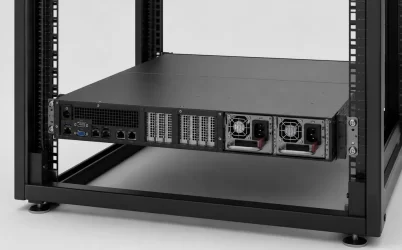
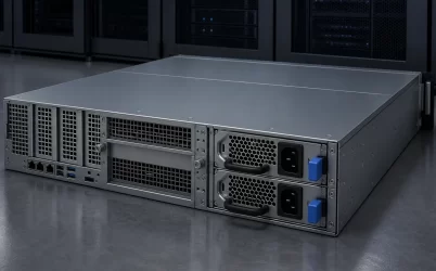
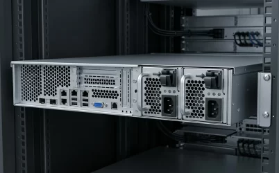
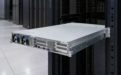
A cloud server power supply alarm should be scoped before a module is replaced. Determine whether the event affects one PSU, one bay, both PSUs in a server, several servers on the same rack feed, or systems across multiple racks. That scope separates a likely module fault from a power distribution board (PDB), management, cooling, rack PDU, or upstream source problem. Preserve logs and operating conditions before changing hardware.
“Cloud server power supply” describes a deployment category rather than one standardized PSU interface. Flex documents AC-DC power-supply solutions for cloud and data-center applications, while the exact module, shelf, output, management, and service behavior remains specific to the platform.
Quick triage: establish the failure scope
Start with five questions: Is one module affected or both? Is the alarm limited to one server? Do neighboring servers share the symptom? Did the incident coincide with a workload, temperature, firmware, or maintenance change? Do the baseboard management controller (BMC), module indicators, rack PDU, and facility event records point to the same time and boundary? Avoid treating an “absent,” “failed,” or “input lost” message as proof that the removable PSU itself is defective.
- One module only: investigate the module, its cord and source, its bay, the mating connector, and its management path.
- Both modules in one server: examine common server-side components, source availability, PDB behavior, host management, and cooling.
- Several servers on one rack branch: move the investigation upstream toward the rack PDU, branch protection, feed, or environmental condition.
- Multiple racks or rooms: correlate UPS, transfer, distribution, and facility events before opening individual servers.
A dual-PSU server may be operating redundantly, may need both modules for capacity, or may use another platform-defined policy. Review what two server PSUs actually protect before assuming that removal or isolation of one source is permissible.
Use the symptom to choose the first boundary
| Observed symptom | Likely boundaries to investigate first | Useful first evidence |
|---|---|---|
| One PSU reported absent or failed | Module, bay connection, assigned input feed, management interface | Exact module identity, BMC event sequence, module indication, cord and PDU outlet state |
| Redundancy degraded but the server remains online | Failed or unrecognized module, source loss, pairing policy, insufficient supported capacity | Active power policy, present load, input status, module inventory and firmware records |
| Both PSUs report input loss or go offline | Shared rack source, PDU branch, server PDB, common cooling or management condition | Neighboring-server status, rack PDU events, upstream alarms, server standby and BMC behavior |
| Repeated failover or intermittent PSU alarms | Loose or damaged connection, unstable source, thermal cycling, current-sharing problem, firmware or telemetry path | Time-correlated logs, inlet temperature, workload state, source measurements and maintenance history |
| Shutdown during high workload | Degraded capacity, input limitation, thermal protection, distribution loss, downstream load transient | Workload timeline, surviving-module state, temperatures, rack-feed events and high-resolution platform data |
| Replacement module not recognized | Unsupported part or revision, seating, bay/PDB contact, pairing rule, firmware or communication path | Approved-parts record, old and new labels, insertion event, BMC inventory and bay inspection |
The table prioritizes boundaries, not conclusions. For example, two simultaneous “input lost” messages could indicate a shared upstream interruption, but they could also result from separate feeds being switched together or from management reporting that does not reflect the exact electrical state. Platform documentation and source-side observations must resolve the ambiguity.
Capture the event before the system state changes
A useful incident record aligns electrical, thermal, workload, and service evidence on one timeline. Begin with the first reliable timestamp rather than the time an operator noticed the alarm. BMC logs, orchestration alerts, rack PDU records, UPS events, and facility monitoring systems may use different clocks or reporting delays, so record their time sources and offsets where known.
Workload and operating state
Record whether the server was starting, idle, running a scheduled job, entering a power-capped state, updating firmware, or recovering from another fault. For virtualized cloud nodes, note migrations, node draining, accelerator jobs, storage rebuilds, and fan-speed changes that occurred around the event. A correlation does not prove causation, but it can distinguish a random module disappearance from a repeatable load- or temperature-dependent failure.
Module and host identity
Capture the server model and configuration, both PSU part numbers and revisions, installed firmware, bay assignments, and the host-reported power policy. Photographing the labels before removal can preserve information that inventory software omits. If one module has recently been replaced, record whether the platform permits that exact revision and mixed-module combination.
Source and environmental state
Record which rack PDU outlet and upstream feed supply each module. Confirm observations at the source rather than inferring them from a server alarm. Also collect inlet temperature, fan status, blocked-airflow observations, rack-door condition, and recent cooling work. A cloud node can report a PSU event when the initiating condition is inadequate cooling or an upstream source interruption.
Stop before undocumented energized probing, improvised pin tests, or live module movement. Continue only under the host manufacturer’s procedure, site electrical-safety rules, and a confirmed continuity plan for the surviving load.
If one PSU is absent, determine whether the fault follows the module
A single-module alarm creates four main suspects: the removable PSU, its input source, the bay/PDB path, and the communication path used by host management. These can produce similar messages while requiring different corrective actions.
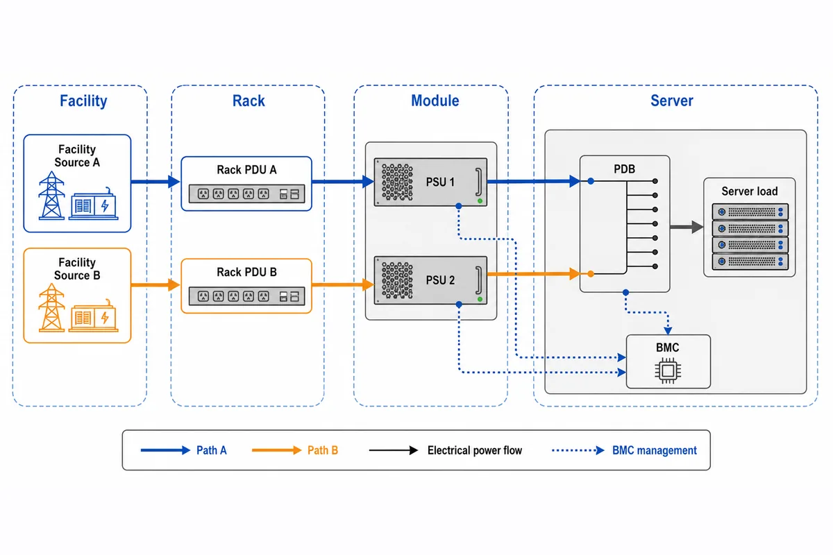
First compare observations that do not alter the running system. Does the affected module have input power at its assigned outlet? Does the rack PDU show an outlet event? Is the module electrically contributing but missing from BMC inventory, or is both power contribution and communication absent? Do the connector, latch, handle, and module position show evidence of incomplete seating or damage? Indicator colors and flash patterns must be interpreted from the exact platform documentation rather than a generic LED chart.
If the host-approved service procedure permits a controlled substitution, the diagnostic value comes from observing whether the symptom follows a known-supported module or remains with the same bay. A fault that follows the module strengthens the case for a module-specific problem. A fault that remains at one bay directs attention toward the mating connector, PDB path, local source assignment, or management channel. This is not conclusive when the replacement differs in revision, firmware behavior, or host support.
A powered module should not be moved merely to perform an experiment. If available redundancy, server load, source state, or hot-swap authorization is uncertain, drain the workload and use the documented shutdown procedure. Protecting service continuity takes priority over obtaining a faster diagnosis.
If both modules fail together, search for what they share
Simultaneous PSU alarms often shift the investigation away from two independent converter failures. Follow the shared boundaries in both directions: upstream toward cords, rack PDU branches, UPS paths, and facility distribution; downstream toward the PDB, common bus, standby supply, motherboard, cooling controls, and management system.
Start by asking whether other equipment on the same branch changed state at the same time. A rack-wide event strongly favors a source-side investigation. A single-server event with healthy neighboring outlets keeps server-side common components in scope. If host management is unavailable, use rack and facility evidence to avoid mistaking loss of telemetry for proof that both modules failed identically.
The PDB is especially important because it combines module outputs and may carry shared standby, control, monitoring, isolation, and downstream distribution functions. A fault in a common path can disable the load or create two module alarms even when neither converter initiated the incident. Powernexu’s explanation of redundant PDB architecture shows why source isolation, current sharing, the common bus, and branch protection create distinct fault boundaries.
Do not assume separate power cords prove source independence. The cords may terminate on the same PDU, branch, UPS, transfer path, or upstream source. Conversely, independent feeds do not eliminate shared server-side components. The incident scope must follow the actual electrical topology, not the number of visible cables.
Repeated failover needs time correlation, not repeated replacement
Intermittent events are difficult because the system may appear healthy during inspection. Replacing a module without preserving a timeline can temporarily suppress the symptom while leaving an unstable source, damaged bay contact, thermal restriction, or shared-path problem in service.
Compare recurrence against four changing conditions:
- Workload: Does the event appear during startup, storage rebuild, accelerator activity, or another repeatable demand transition?
- Temperature and airflow: Does it occur after inlet temperature rises, fans change state, filters or doors restrict airflow, or adjacent equipment alters exhaust recirculation?
- Input source: Do rack PDU or upstream events coincide with the module alarm, even if the interruption is too brief for a slow dashboard to display clearly?
- Service state: Did the behavior begin after a module replacement, firmware update, rack move, cable change, or PDU maintenance event?
A load-correlated shutdown might result from insufficient supported capacity after one module drops out, a source disturbance, thermal protection, a poor high-current connection, PDB behavior, or a downstream transient. BMC averages alone should not be presented as proof of a short-duration mechanism. Escalation may require platform-vendor diagnostics or appropriately instrumented measurement performed under an authorized test plan.
A replacement is successful only when the host restores the intended state
Physical insertion does not prove recovery. A visually similar PSU may have a different interface implementation, revision, output capability under the deployed input, airflow direction, firmware relationship, or platform approval status. Use the server’s supported-parts documentation or an explicitly documented supersession rather than selecting by wattage and shell shape.
If a replacement is not recognized, preserve the original and replacement label records, then investigate the event in layers. Confirm that the part and revision are supported for the host, that the platform permits the installed pair, and that the module is fully seated under the approved procedure. Inspect the bay and mating area only as permitted, without touching energized contacts. Review whether management detected an insertion event, whether the module reports input presence, and whether firmware or configuration changes are required by the platform.
After corrective action, look for agreement among several forms of evidence:
- the host inventory identifies both supported modules in their expected bays;
- the active power or redundancy policy reports the intended protected state;
- both assigned input paths are present and correspond to the documented rack feeds;
- no continuing share, input, temperature, communication, or mismatch alarms remain;
- the server supports its permitted workload without repeating the original event; and
- the replacement identity and incident record are retained for fleet and spare management.
If the server returns to service but management still reports a degraded pair, the incident is not resolved as a redundancy event. Likewise, clearing an alarm by rebooting does not establish whether the initiating boundary was the module, PDB, source, cooling system, or management path.
Escalate with a boundary statement, not a generic PSU complaint
Escalation becomes more effective when it states what is known and what remains unresolved. A useful report might say that the fault follows one exact module across an authorized substitution, that it remains with one bay using two supported modules, that both modules lose input when a particular rack branch records an event, or that the shutdown repeats only during a named workload and inlet-temperature condition.
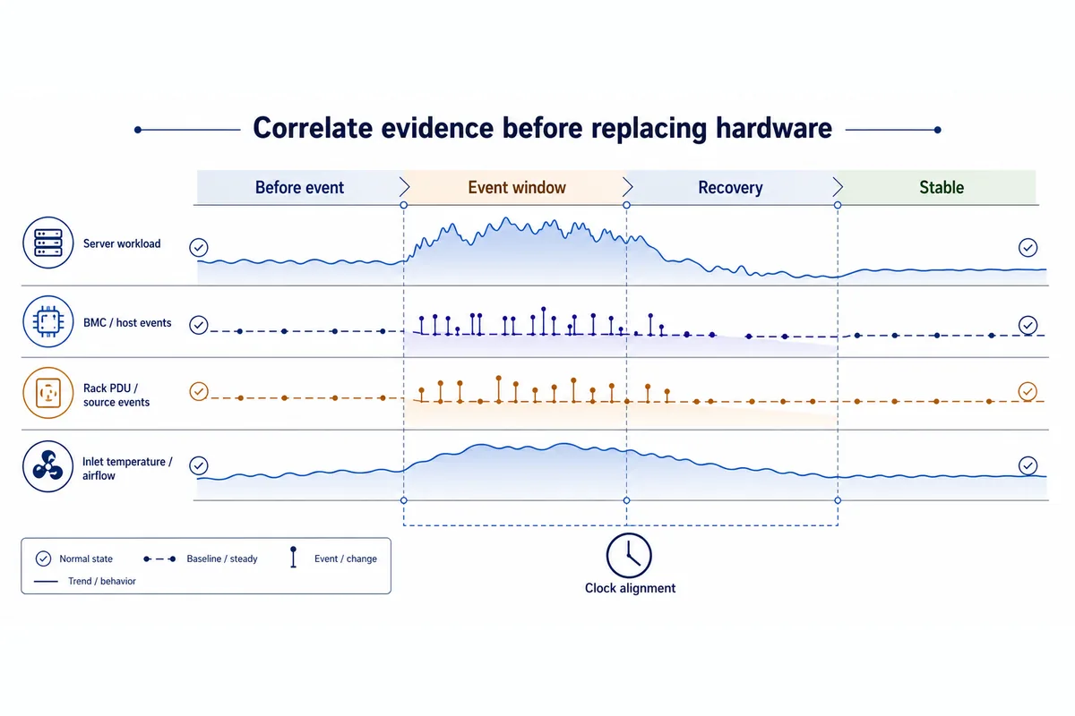
Stop local troubleshooting when the next step would require undocumented energized access, an unsupported part, uncertain surviving capacity, opening a protected enclosure, defeating interlocks, or probing an unidentified connector. Also escalate when BMC, rack PDU, and facility records disagree materially; that conflict is evidence that the failure boundary has not yet been isolated.
The strongest resolution identifies both the failed boundary and the restored operating state. For a module fault, that means a supported replacement recognized by the host and a genuinely restored redundant pair. For a bay or PDB fault, it means correcting the shared server path rather than consuming more PSU spares. For a rack or facility event, it means tracing the interruption upstream while preserving evidence from affected servers. That distinction turns a broad cloud server power supply alarm into an actionable module, server, rack, or facility incident.