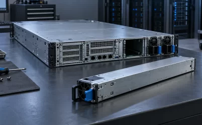
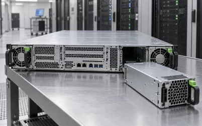
A redundant power supply and a UPS solve different interruptions. Two server PSU modules can keep the server running when one module fails, provided the remaining module and power path can carry the load. A UPS can keep supplying AC when its upstream utility source disappears, but only within its supported load and available runtime. A server with two PSUs plugged into one unprotected strip may survive a PSU fault yet shut down in a power outage. A single-PSU server behind a UPS may survive that outage but still stop when its only PSU fails. The practical question is not which device is “more redundant”; it is which failure must leave the workload running.
Different failures reach the server at different points
A server’s power chain starts upstream of its removable PSU modules. Utility or generator supply reaches a switchboard, perhaps a UPS, then rack distribution, cords, PSU inputs, and finally the DC bus feeding the host. A second module is placed near the end of that chain. It does not create a second source of energy at the start. The UPS sits earlier and can bridge a loss of its own incoming source, but it does not repair a failed converter inside the server.
The distinction is easiest to see with four events. If one PSU develops an internal fault, a genuinely redundant module pair may leave the DC bus energized. If the facility loses utility power, a correctly sized UPS may take over for its specified runtime. If a rack PDU fails, the outcome depends on whether the server’s PSU cords terminate on independent paths; neither a dual-PSU badge nor a UPS label proves that they do. If the common PDB or motherboard-side power path fails, adding a second PSU or a single upstream UPS may leave the same common point exposed.
That is why “redundant” needs a named boundary. Module redundancy concerns conversion hardware. Feed redundancy concerns the AC path to each input. UPS redundancy concerns availability within the backup-power system itself. These boundaries can coexist, but one is not a substitute for another.
What a second PSU actually buys
In a 1+1 server arrangement, each installed PSU must be capable of supporting the required host load after the other is lost under the specified operating conditions. During normal operation the units may share power, or a platform may run one more heavily. The exact control behavior is platform-dependent. What matters in the fault state is that the surviving converter, its inlet, connector, distribution path, and cooling can support the load the host still demands. Two nameplate ratings should not simply be added and treated as redundant capacity.
Removing a hot-plug module while the host stays online is a useful service capability, but it is not itself proof of N+1 operation. A model may physically slide out even when the installed capacity or configured workload will not survive its removal. Management software may respond to a missing PSU by capping CPU or accelerator power; other systems may shut down. The server’s supported PSU pairing, input range, load policy, and management state determine the actual outcome.
Independent upstream sources improve a dual-PSU design. If both PSU cords land on the same rack PDU and branch circuit, a PDU or breaker fault can remove both inputs at once. Connecting them to separately protected A and B paths can preserve power after one path is lost, provided the surviving path has enough capacity. Where both A and B ultimately depend on a single UPS cabinet or a common bypass, they still share a deeper failure domain. The diagram used for design should show that convergence rather than stopping at two colored cords.
A redundant PSU therefore answers a precise question: “Can this host continue when one specified converter or input path goes away?” It does not answer how many minutes the host runs after a site-wide utility outage. That second question belongs to upstream energy storage and its supporting controls.
What a UPS adds—and what it cannot promise
An uninterruptible power supply conditions or transfers power according to its design and uses stored energy, typically batteries, to support a load when its incoming supply is unavailable. UPS topology and operating mode matter: the behavior of an online double-conversion system, a line-interactive unit, and a bypass event should not be compressed into one universal “zero interruption” claim. The supported transfer behavior and downstream equipment tolerance must be checked for the specific equipment.
A UPS is specified by both the load it can support and the duration for which it can do so under stated conditions. Those are separate quantities. A larger server load generally shortens available battery runtime; battery age, temperature, configuration, and the selected UPS operating state also affect the result. Eaton’s UPS sizing guidance explicitly treats connected load and runtime as distinct sizing considerations. A headline UPS power rating is not a runtime promise.
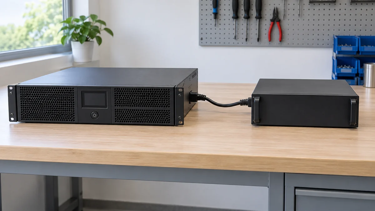
For a hypothetical planning case, imagine one server and its essential network device together draw 700 W of AC input at the UPS output. That number is the load to carry during an outage, not a “700 W PSU rating” and not the UPS’s available energy. To estimate runtime, use the manufacturer’s runtime curve or configuration tool for the actual battery set at that load, including any other devices connected to the same UPS. Dividing a nominal battery watt-hour label by 700 W would ignore conversion losses, battery discharge behavior, reserve limits, and the manufacturer’s supported operating range; it is not a defensible promised runtime.
UPS backup is often intended to bridge the interval until a generator assumes the load or to allow an orderly shutdown. A longer runtime requires suitable energy storage and load management, not simply another server PSU. Conversely, a UPS may supply perfect AC at the rack while a failed sole converter leaves one server down. It protects a different segment of the chain.
Follow the outage rather than the equipment labels
Suppose a dual-PSU server has two cords, but both are connected to outlets on one UPS-backed rack PDU. During a utility outage within UPS runtime, both inlets may remain energized. During a failure of either server PSU, the remaining unit may carry the host. Yet a failure of that rack PDU or its common upstream outlet removes both server inputs. The architecture has module resilience and utility-bridge capability, but not two independent rack distribution paths.
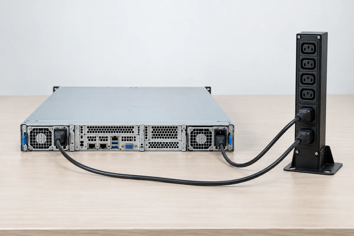
Now separate the cords: PSU A receives one protected distribution path and PSU B another. If the paths have independent breakers and PDUs, one PDU fault need not remove the host. If each path is backed by an independent UPS system, the design also reduces the chance that one UPS fault removes both inputs. This is a system architecture, not a feature conferred by buying any particular two-port UPS or server. It must account for common upstream switchgear, bypass, generator controls, rack connections, and the host’s surviving-module capacity.
The opposite configuration can be reasonable for a less critical workload: a single-PSU machine on a UPS whose outage runtime is sufficient for graceful shutdown. It has no converter redundancy, but it may protect against the event the owner actually expects to manage: an upstream power interruption. Calling this inferior merely because it has one PSU would hide the deployment objective. The machine still needs a replacement or recovery path if that PSU fails.
The key comparison can be read as a series of conditional outcomes rather than a winner-takes-all chart:
| Event | Second server PSU | UPS | Remaining condition |
|---|---|---|---|
| One PSU module fails | May preserve the host if capacity and isolation are sufficient | Does not replace the failed converter | Surviving PSU and host policy support the load |
| Incoming utility supply is lost | Cannot supply energy by itself | May bridge the event within supported runtime | UPS load, battery state, and operating mode fit the event |
| One rack feed fails | May preserve the host when fed from an independent surviving path | Only helps if placed on a path that remains available | A/B paths are genuinely separated upstream |
| Common PDB or host power path fails | May not help | May not help | Fault containment depends on host design |
The table is intentionally conditional. Fault isolation, module current sharing, UPS transfer, battery condition, and upstream independence are product- and site-specific. A diagram showing those boundaries is more informative than a list of equipment names.
Two clocks: instantaneous continuity and outage runtime
A PSU module fault is an electrical and control event on a short time scale. Output hold-up, current sharing, fault isolation, and host power policy govern whether the DC bus remains in its allowed range as one module disappears. “Hot swap” describes a supported replacement operation after continuity has been established; it is not a battery reserve. The host should not be assumed to survive solely because the spare PSU can be inserted without shutting down in a different configuration.
An upstream outage asks a different timing question. The UPS must maintain an acceptable output while its input is absent or changing, then support the connected load until utility returns, generation is available, or systems shut down. In this interval the server may still experience workload peaks. A runtime estimate made at a low idle load can be misleading if the actual protected load includes network switches, storage, or a busier server state.
A clean architecture discussion keeps these clocks separate. First, will the host’s DC load remain supplied through a local PSU fault? Second, will AC be available at its inlets through the facility event? Third, how long must the whole dependent workload remain available? The answers can drive different equipment decisions and different operating procedures.
The hidden common points in a “dual everything” rack
Duplicated hardware can still converge on one vulnerable component. Two PSUs feeding a single PDB share the board and its distribution path. Two rack PDUs fed from the same branch circuit share its breaker. Two UPS cabinets supplied through one transfer or bypass arrangement may share that point. The purpose of tracing the chain is not to imply every installation needs fully separate utility services; it is to know which event each claimed level of continuity actually covers.
One especially confusing label is “redundant UPS.” It may mean N+1 modules inside a UPS system, two parallel UPS systems, or separate A/B UPS-backed paths. Those are different topologies with different common components. The server still needs enough inlet paths and converter capacity to take advantage of them. Likewise, a dual-cord server does not imply that its two inputs have independent batteries upstream. The wiring diagram, rather than the sales adjective, establishes the fault boundary.
Matching the protection to the workload
For a dual-PSU server, the useful specification question is whether one approved module can carry the host’s expected fault-state demand at the actual input and thermal conditions. For a UPS, it is whether the complete protected AC load—including equipment that the server depends on—can be supported for the required interval. Both questions can be answered without claiming that a PSU’s output watts equal a UPS’s AC load watts. Conversion losses and the rest of the protected equipment separate those numbers.
A single UPS feeding both server PSUs is a coherent design when the aim is to bridge utility interruptions and tolerate one PSU failure, and when the owner accepts the UPS and rack feed as common points. If the aim includes surviving a UPS or PDU fault, independent paths are needed farther upstream. That is the useful distinction behind “redundant power supply vs UPS”: one protects against a specified conversion-path loss; the other supplies temporary upstream energy. Reliable continuity comes from placing each protection at the failure boundary that matters, then naming the common points that remain.