CRPSHD2000D2 is a 2,000 W, 12 V CRPS module with two published input families: 90–264 Vac and 180–400 Vdc. Its high-voltage DC range is the reason to examine this exact HD model rather than assume that a similarly rated AC-focused CRPS is interchangeable. The Powernexu CRPSHD2000D2 product record and the Great Wall manufacturer listing agree on the stated envelope. Neither public listing assigns the three published 12 V current figures to particular inputs. That missing mapping matters before anyone calls a 2,000 W module a 2,000 W solution on a particular feed.
Start with the DC bus, not the wattage label
A rack designed around a high-voltage DC bus has an upstream electrical boundary that an ordinary AC supply does not automatically cross. CRPSHD2000D2 explicitly lists 180–400 Vdc alongside its 90–264 Vac input range. That makes it a candidate for a compatible high-voltage DC distribution system and for an AC-powered system, subject to the correct inlet, mating interface and application approval. The public range does not itself certify any particular rack bus, plug, polarity scheme or live insertion procedure.
At 180 Vdc, delivering 2,000 W at the output would require more than 11.1 A at the input even with impossible 100% conversion efficiency. At 400 Vdc, the corresponding ideal minimum is 5 A. Real input current is higher because conversion has losses, and peak, startup and transient behavior require separate design margins. These simple bounds show why a DC feed cannot be sized from the output wattage alone. They are arithmetic examples, not a manufacturer current specification.
The 180 Vdc lower limit matters if a distribution bus dips during discharge or transfer. Nominal voltage within range does not prove every excursion is within range. Record actual voltage at the module interface across expected states; a bus below 180 Vdc is outside the published DC window.
The AC figure should be interpreted independently. A 90–264 Vac acceptance range does not guarantee full 2,000 W output at each point in that range. The output-current row suggests operating tiers, but the listing does not state their input conditions. A system that may run on both AC and DC needs the approved capacity and transfer behavior for each feed, not just evidence that both voltage numbers appear on the page.
Three 12 V figures are not three simultaneous rails
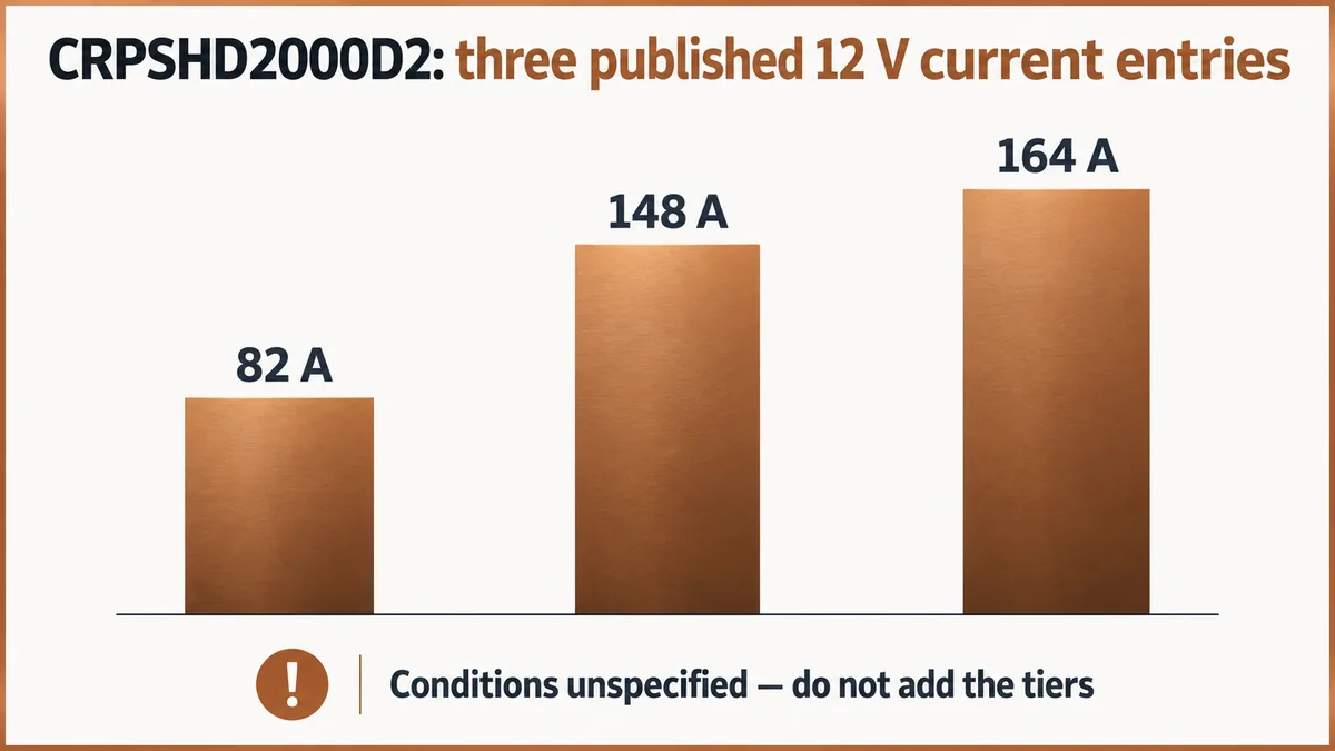
The manufacturer lists +12 V / 82 A, +12 V / 148 A and +12 V / 164 A. At nominal 12 V, these correspond to 984 W, 1,776 W and 1,968 W. The listing does not say these values are additive, separate rails or selectable modes. They are distinct published limits with unspecified conditions.
That distinction changes a server capacity calculation. If a platform is designed for a 1,500 W sustained 12 V demand, 148 A at 12 V provides a nominal 1,776 W arithmetic ceiling, whereas 82 A gives only 984 W. The difference is large enough to change whether the module is suitable for the load. Yet choosing the 148 A row without knowing its input and environmental conditions would be an unsupported step. Obtain the full model datasheet, nameplate or written manufacturer confirmation tying each current tier to input voltage and operating temperature.
The +12 VSB / 3 A output is separately listed. It supports the standby architecture in a compatible host, but the public table does not define how standby consumption is accounted for within total rated output, nor does it describe sequencing or connector pin assignments. A 36 W arithmetic standby maximum is useful for an initial budget; it is not permission to add 36 W to a continuously available 2,000 W main load. The host’s standby demand and control interface must be checked against the actual module documentation.
At the highest listed 164 A main-output current, small resistance becomes consequential. For illustration, 1 milliohm in a current-carrying path would dissipate about 26.9 W at 164 A, using I²R. That does not describe the resistance of this module or any particular connector. It explains why mating contacts, a distribution board and copper geometry need a rated design rather than a visual judgment that the plug “looks like CRPS.” The current path must also accommodate fault and transient behavior set by the final system.
The 185 mm body defines only part of the interface
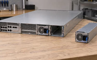
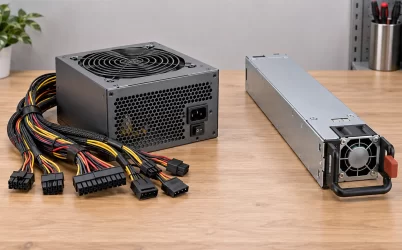
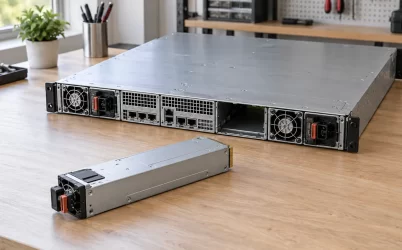
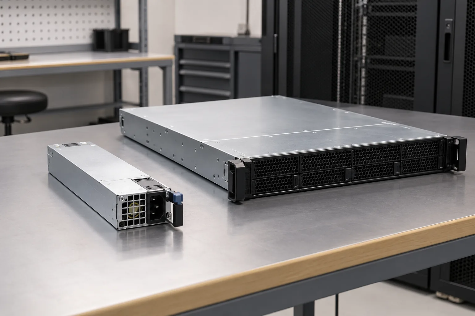
CRPSHD2000D2 is listed at 185 × 73.5 × 40 mm. These dimensions describe the module envelope, which helps screen a candidate bay. They do not disclose the connector key, pinout, latch, handle clearance, guide rails, insertion depth to the electrical contacts or firmware expectations. A mechanically similar CRPS module can still fail electrical, thermal or management compatibility.
For a replacement project, compare the complete existing part number and revision with the proposed HD module. The host’s power distribution board needs an interface rated for the relevant 12 V current tier and standby arrangement. A server controller may also expect specific power-good, presence or telemetry behavior. The manufacturer listing does not publish those details for CRPSHD2000D2, so an integration drawing or host compatibility record is the appropriate evidence. The dimensions alone support a preliminary fit check, not a drop-in claim.
Airflow is listed as FR. The abbreviation identifies the manufacturer’s published direction; the chassis still needs a matching intake and exhaust path. Check the orientation against the actual module drawing and rack cooling scheme before specifying a spare. A reversed airflow module in a physically identical shell can defeat the intended cooling path. The listed operating-temperature interval is 0–55°C, but the public row does not supply a derating curve. Do not extend the maximum current to 55°C by assumption.
A useful physical comparison can be made without pretending that all CRPS families are the same. The HD2000D2’s published depth is 185 mm. That sets one envelope constraint. Its higher-voltage DC acceptance sets another, independent constraint. A host that accepts the first but not the second, or the second but not the complete electrical interface, has not established compatibility. The model suffix is therefore part of the engineering identity, not an optional procurement shorthand.
Where the HD model differs from nearby CRPS choices
The CRPSHD family is useful to compare on input architecture. The Powernexu listing places the 800 W, 1,300 W, 1,600 W and 2,000 W HD models in a family with the same stated 180–400 Vdc range. That suggests a power-level progression for a high-voltage DC platform, but it does not establish common firmware, connectors or approved interchangeability among them. A platform may qualify more than one rating; such qualification must be documented by the platform owner.
A conventional CRPS model with a similar 2,000 W number may list a different DC range, or none at all. For instance, a 180–320 Vdc upper limit and a 180–400 Vdc upper limit are different when the bus can approach 400 Vdc. A system operating at 380 Vdc cannot rely on the lower range merely because both supplies are called “CRPS” and fit a similar mechanical bay. The suffix and exact input row control this comparison.
Power level also does not determine an approved redundancy arrangement. Two 2,000 W modules in a 1+1 system do not create 4,000 W of protected load; the surviving module must carry the load under the actual feed and temperature conditions. If a current tier limits a module to approximately 984 W at a given condition, that condition may set a much lower protected system load than the headline rating suggests. Use the manufacturer’s tier mapping, then apply the host’s distribution and thermal limits. The article’s current-to-watt conversions are only nominal arithmetic.
Consider the feed itself as a separate failure domain. AC and high-voltage DC inputs may be alternatives for the module, but the listing does not promise seamless transfer between them within a single installed unit. Whether a platform uses separate supplies on independent feeds, transfer equipment upstream, or a single source is a system architecture choice. The published input ranges do not disclose hold-up time, transfer interruption tolerance or hot-plug behavior on a DC bus.
How to turn the public specification into an actual part decision
Begin with the power source the machine will really see. For AC, identify the expected minimum and maximum at the PSU inlet, including low-line operation. For DC, identify nominal bus voltage, regulation tolerance and expected excursions at the connector. Compare those conditions with 90–264 Vac and 180–400 Vdc respectively; do not merge the two numbers into one universal input range. The public record establishes voltage acceptance categories, while the final electrical design needs the missing current and transient data.
Next, translate the host load into current at 12 V rather than looking only at a total watts figure. Separate sustained demand from startup and short transients. Count the distribution board, connector and any local conversion stages in the path. For example, 1,700 W delivered on a nominal 12 V bus implies roughly 142 A before considering losses beyond the module output. That load exceeds the published 82 A figure, fits under 148 A arithmetically and fits under 164 A arithmetically. Only the conditions attached to those tiers can settle which comparison applies.
Then resolve the mechanical and control interfaces using the actual host drawing. Verify the complete 185 × 73.5 × 40 mm envelope, extraction space, latch, mating connector and standby or signaling pins. The host manufacturer may specify an approved PSU list or a firmware requirement. That list carries more weight for a replacement than a generic claim that the part is CRPS-sized. If the host lacks published compatibility data, request it from the platform vendor or the supply manufacturer rather than inferring interchangeability.
Finally, align the environment with the published FR airflow and 0–55°C operating interval. The relevant temperature is the air the module receives, not simply the room thermostat reading. A dense shelf can deliver warmer inlet air to a module than the room setpoint. Since no public derating curve is tied to the three current tiers, the high-temperature capacity needs confirmation. Platinum is the listed efficiency class, but without a model-specific load curve it cannot be converted into a precise heat-loss or electricity-cost promise for this installation.
A 380 Vdc rack exposes the model’s real advantage and its open question
Suppose a rack has a regulated 380 Vdc bus and a server with a 1,600 W sustained 12 V demand. The published 180–400 Vdc acceptance interval includes the nominal bus, making CRPSHD2000D2 a plausible candidate where a unit limited to 320 Vdc would be outside its stated range. The nominal output current for that load is about 133 A. It exceeds the listed 82 A tier and sits below the 148 A and 164 A tiers. The public product row alone cannot confirm that either higher tier is available at 380 Vdc and at the server’s actual inlet temperature.
That example points to a specific request rather than a generic request for “more information”: ask Great Wall or the platform vendor for the CRPSHD2000D2 power-versus-input table and any temperature derating, plus the approved mating interface. With those in hand, the rack designer can decide whether 1,600 W is supportable on the 380 Vdc feed, whether a redundant survivor can carry it, and whether the physical module is an approved part for the server. Until then, the correct conclusion is narrower: the voltage range matches the nominal bus, while full-load and host compatibility remain unverified.