A server power supply can shut down correctly during a fault and still leave a damaged connector or an unavailable server. Protection features respond to particular electrical or thermal conditions at particular sensing points. They do not establish that every component downstream remains inside its own limits. Understanding server power supply protection features therefore starts with two questions: what condition does the PSU detect, and which part of the power path does its response actually protect?
The familiar abbreviations cover overvoltage, undervoltage, overcurrent, overpower, short-circuit, and overtemperature protection. A product may document some functions separately, combine several under one control mechanism, or describe behavior without using the abbreviation. A useful comparison connects each function to its monitored quantity, affected output, response, reporting, and recovery conditions. Counting acronyms gives a much weaker picture.
Six abbreviations describe different abnormal conditions
Overvoltage protection, or OVP, responds when a monitored voltage rises beyond its protection threshold. It is distinct from normal voltage regulation: regulation holds an output near its setpoint during supported operation, while OVP addresses an abnormal excursion. A load can have a tighter acceptable voltage range than the PSU’s shutdown boundary, so an OVP entry alone does not prove that a particular motherboard or accelerator is protected against every damaging excursion.
Undervoltage protection, or UVP, addresses voltage below a defined boundary, but the location matters. Input undervoltage lockout prevents conversion outside supported input conditions. Output undervoltage supervision concerns a low DC rail. An input shutdown specification cannot be substituted for an output UVP specification. Similarly, a power-good signal becoming inactive may inform the host that an output is invalid without describing a separate protective shutdown mechanism.
Overcurrent protection, or OCP, responds to excessive current in the monitored path. Overpower protection, or OPP, responds to excessive power, which involves voltage and current. On a tightly regulated single output, the two may appear closely related during a steady overload. They still should not be treated as interchangeable specifications: sensed quantities, delays, affected rails, and behavior during voltage collapse can differ.
Short-circuit protection, or SCP, addresses a low-impedance output fault. A short may be handled through the current-protection system rather than a separately advertised circuit. Overtemperature protection, or OTP, responds to a monitored temperature condition. Neither abbreviation identifies the exact sensor location or proves that a distant cable terminal, distribution-board component, or processor voltage regulator remains cool enough.
| Function | Quantity or condition | Boundary needing clarification |
|---|---|---|
| OVP | Excessive voltage | Output, sensing point, threshold, and response |
| UVP | Insufficient voltage | Input lockout, output supervision, or output shutdown |
| OCP | Excessive current | Module current, one rail, or a protected branch |
| OPP | Excessive power | Individual or combined outputs and time window |
| SCP | Low-impedance output fault | Supported fault conditions and current-protection interaction |
| OTP | Excessive sensed temperature | Sensor location, warning relationship, and recovery |
A real datasheet separates functions by output
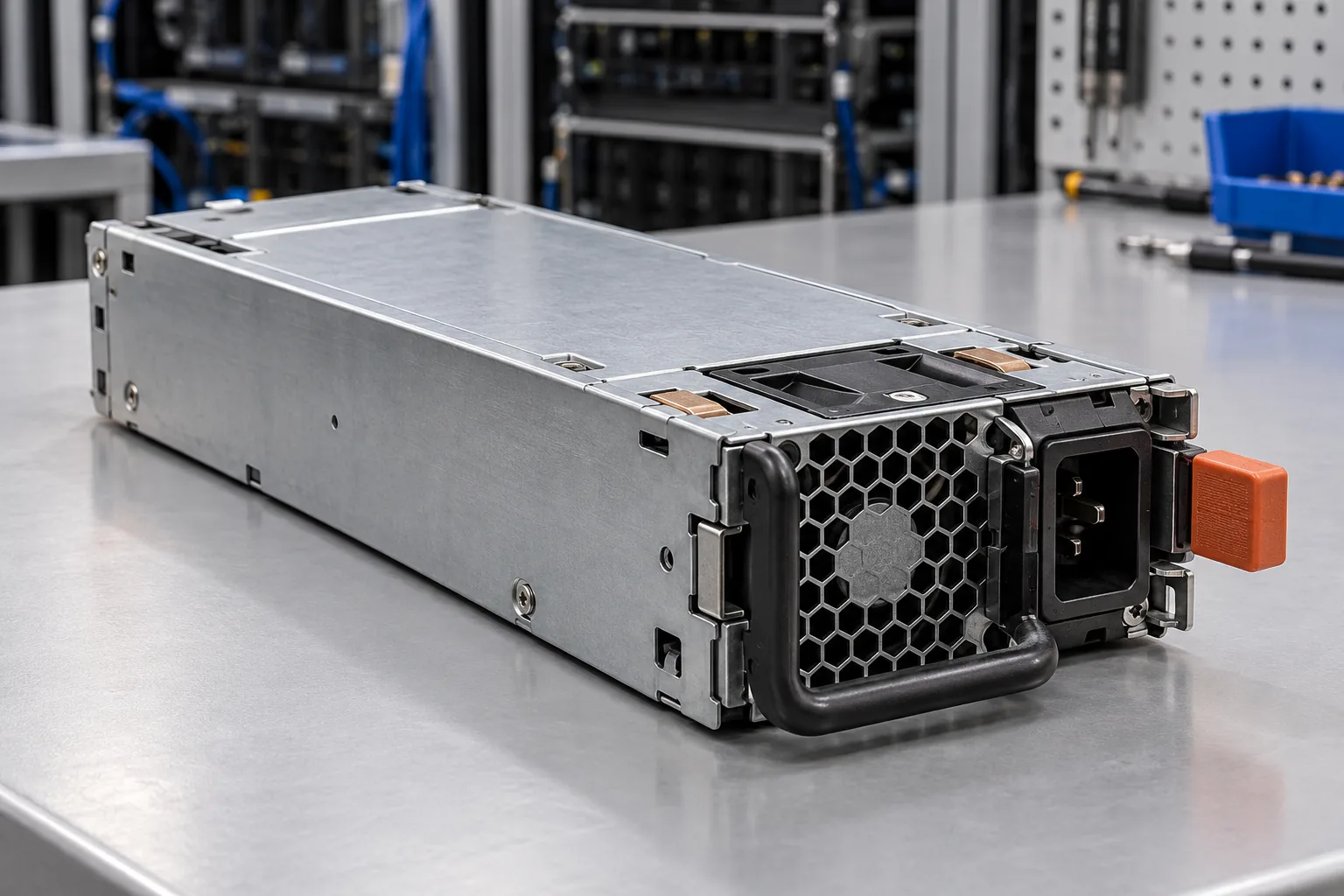
Murata’s D1U54P-W-450-12-HxxC series provides a useful example of why the detailed table matters more than the feature heading. Its manufacturer datasheet, revision D1U54P-W-450-12-HXXC.A07.D03, lists overvoltage, overcurrent, and overtemperature protection. The ordering guide distinguishes D1U54P-W-450-12-HA3C and HA4C versions with a 5 V standby output from HB3C and HB4C versions with a 12 V standby output. Those suffixes are part of the evidence, rather than optional naming details.
The Murata protection characteristics table identifies latching overvoltage protection for the main output and separately describes standby-output protection. It also describes an intake overtemperature function with automatic restart and hysteresis. These statements show that one module can contain different recovery policies for different faults. They do not support a universal statement that every protection event in a server PSU behaves alike.
There is another useful distinction in this document: the main-output overcurrent entry is marked as a target. A target should retain that qualification when copied into a comparison or purchasing requirement. Removing it converts a qualified manufacturer statement into an apparently firm acceptance limit. This article does not use that target to establish a guaranteed trip point or compute usable overload capacity.
The cited table does not establish separate UVP, OPP, and SCP specifications simply because those abbreviations commonly appear in discussions of power supplies. Their absence from that table is a documentation boundary, not proof that the converter lacks every related control function. Confirm the required behavior with the manufacturer instead of adding missing acronyms from a generic explainer. This front-end converter example also does not establish approval for an arbitrary server chassis.
The sensing point defines the protected territory
Consider a server PSU feeding a common DC bus, followed by several motherboard and accelerator branches. Module OCP observes current in its monitored output path. A damaged branch connection can dissipate heat while total module current remains below the PSU’s protection threshold. For a resistive connection, local heating follows current squared times resistance; rising connection resistance can therefore create a local problem without a corresponding increase in total server demand.
This is why PSU protection and branch protection solve different problems. The PSU must manage abnormal conditions within its documented output capability. A downstream fuse, electronic breaker, or other coordinated protective element may be needed for the conductor and load on an individual branch. Its suitability depends on the actual current path and fault energy. A PSU feature list supplies neither the branch conductor rating nor evidence of selective fault isolation.
The same spatial issue applies to voltage. Regulation at the output connector does not eliminate voltage drop across distribution resistance. Remote sense, where provided and correctly integrated, changes the regulation reference but does not make every downstream node identical. The OVP sensing arrangement and consequences of a sense-wire fault require their own documentation; the presence of remote sense is not evidence of a particular protective response.
Temperature has an especially clear boundary. An intake sensor measures a condition at the inlet, while internal sensors represent their own locations. A hot connector elsewhere in the chassis may not produce a corresponding sensor reading soon enough to trigger OTP. Conversely, a PSU thermal warning can reveal a problem in its cooling path while other server temperature readings look ordinary. Sensor location gives the reading meaning.
Protection limits are different from operating limits
A protection threshold is not an invitation to run continuously just below it. The supported operating envelope comes from rated output, regulation, input conditions, cooling requirements, and applicable derating. Protection is a response to abnormal operation beyond a defined boundary. Using the trip threshold as an extra performance allowance can leave the converter outside its documented continuous capability even though it has not shut down.
Compare limits as ranges with conditions, rather than isolated numbers. A minimum and maximum trip boundary describe allowed variation, not two selectable settings. A typical value is not a guaranteed worst case. The relevant input voltage, temperature, output combination, and transient duration may also matter. Where a document provides only a feature name, the omitted conditions remain unknown.
Response timing is equally important. A brief supported load excursion and a sustained overload need not produce the same result. Normal transient-response data describe voltage behavior under specified load changes; those data do not automatically define protection-trip timing. Likewise, a shutdown threshold does not describe the complete waveform presented to the load before shutdown. Matching a sensitive load requires evidence appropriate to that load’s tolerance.
Two supplies can therefore list the same six features and offer substantially different behavior. One may provide detailed per-output limits and fault timing; another may provide only a general protection statement. The second document does not justify filling its gaps with values from the first, even if the housings and power ratings resemble one another.
A comparison also needs to identify which document controls the claim. A family brochure may describe options that an individual suffix does not contain. A preliminary table may later change. Keep the exact model, document revision, and any manufacturer qualifications attached to the protection entry. When a required behavior is undocumented, record it as an unresolved requirement rather than marking the feature present because a related product provides it. This preserves a useful distinction between evidence and expectation.
A fault indication is an observation, not a diagnosis
Server platforms may receive PSU information through LEDs, hardware status signals, and a management interface. These channels answer different questions. A presence indication concerns module installation. A power-good indication concerns output validity according to its defined logic. A warning or fault alert asks the host to investigate an abnormal condition. None is a universal substitute for the others.
The Murata example documents both hardware status signals and PMBus-related status indications. That supports describing the available reporting paths, but not assuming that every desired command, threshold adjustment, event history, or management-controller interpretation is implemented. A platform can expose less information to an operator than the PSU makes available internally. Firmware and system documentation determine what the service interface actually reports.
A low output voltage can be the consequence of current protection rather than the initiating fault. A thermal shutdown can follow a cooling failure rather than excessive electrical demand. Several status observations can therefore belong to one event. Preserve their sequence where the platform supports it: an earlier warning, a later output-invalid indication, and a reboot message have different diagnostic value.
Operational records should distinguish measured data from inferred causes. Record the exact PSU model and suffix, active module count, reported fault text, workload state, and relevant platform logs. Avoid translating an amber LED directly into a specific failed component without the model’s indicator definitions. Useful evidence narrows the investigation; a familiar acronym should not prematurely close it.
Shutdown contains a fault; recovery restores service
Protection success and service continuity are separate outcomes. A module that disables its output may have performed its protective function while interrupting the server. Whether another PSU carries the load depends on the supported system architecture and available surviving capacity. A redundancy label does not establish that an overloaded or shorted downstream branch will be isolated from the shared bus.
Recovery also has its own boundary. Automatic recovery means the supply can attempt to resume under documented conditions; it does not establish that the underlying fault has disappeared. A latched response requires the specified clearing action. The deeper distinction between repeated attempts and a retained shutdown is covered in Powernexu’s discussion of a server PSU that stays off after an overcurrent trip. Reset instructions should come from the exact PSU and server service documentation.
For ordinary operations, investigate an event through approved service procedures and existing telemetry. Do not deliberately short live server outputs, obstruct cooling to force OTP, or raise a rail to discover an OVP threshold. Controlled protection characterization belongs in a suitably equipped laboratory with a manufacturer-supported method. A production workload observation is not a substitute for that characterization.
The most informative protection description reads as a causal statement: this output is monitored at this boundary, this abnormal condition causes this response, and the host receives this indication before recovery occurs under these conditions. Any missing part is a specific engineering question. That description makes a protection feature useful without promising that a shutdown circuit can protect every component or preserve every running workload.