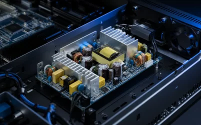
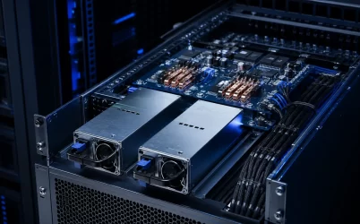
An industrial power supply is a system component, not a commodity selected by output wattage alone. It converts the available facility or machine input into regulated DC power for controllers, sensors, communication devices, relays, actuators, test hardware, and embedded electronics. The right unit must support those loads while operating within the electrical, thermal, mechanical, and environmental limits of the equipment.
Selection mistakes often appear only after installation. A supply may work on a bench but reset a controller when a contactor closes, overheat inside a crowded enclosure, interfere with sensitive signals, or lose usable output at elevated temperature. A reliable design therefore starts with the complete power path and the real operating environment.
Choose the Package for the Equipment Architecture
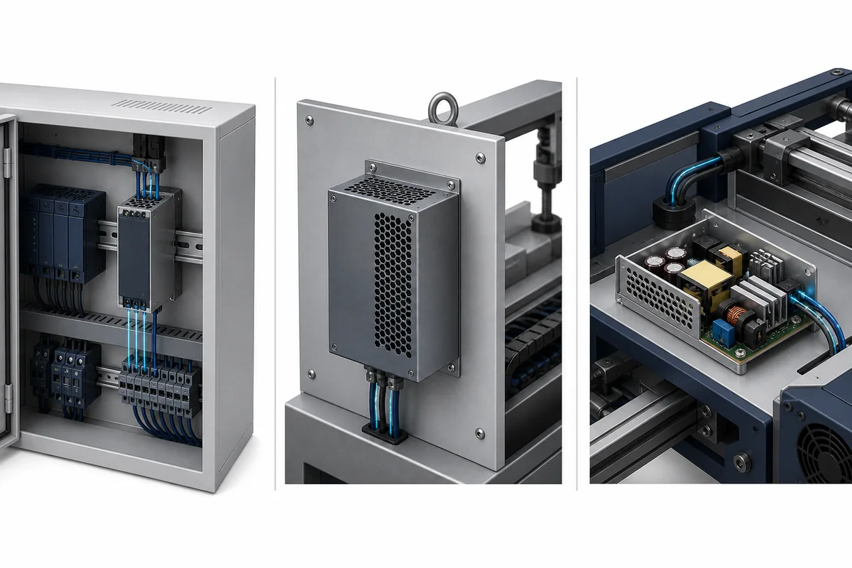
Industrial AC-DC power supplies are available in several mechanical formats. DIN-rail units are designed for organized control cabinets, where standard mounting and accessible terminals simplify installation and replacement. Enclosed chassis supplies suit machine panels, test systems, displays, and embedded industrial equipment that provide their own mounting surface. Open-frame supplies are commonly integrated inside OEM equipment, where the equipment designer controls guarding, airflow, spacing, grounding, and user access.
| Format | Typical integration | Primary design responsibility |
|---|---|---|
| DIN rail | Automation and process-control cabinets | Rail space, terminal access, cabinet airflow, and wiring segregation |
| Enclosed chassis | Machinery, test equipment, displays, and industrial electronics | Mounting, protective earth, ventilation, cable routing, and service access |
| Open frame | OEM equipment with a controlled internal enclosure | Safety barriers, clearances, cooling, contamination control, and compliance of the finished system |
Package style does not determine electrical suitability. Two supplies with similar output ratings may have different input ranges, cooling requirements, protection behavior, connector systems, and installation restrictions. Mechanical choice should narrow the field, but the exact datasheet and application conditions must decide the final model.
Build a Load Budget That Includes Dynamic Demand
Begin with the required DC output voltage, then list every load connected to the supply. Include PLCs, distributed I/O, HMIs, industrial computers, network switches, sensors, transmitters, relays, solenoids, valves, brakes, and any downstream DC-DC converters. Use credible maximum demand rather than the sum of typical values alone.
Industrial loads are rarely constant. A relay coil, motor brake, valve, actuator, lamp, or capacitive electronic input can draw a short startup or switching current that is much higher than its settled demand. Several loads may also start together after power is restored. The supply must tolerate the actual sequence without excessive voltage drop or unintended protection operation.
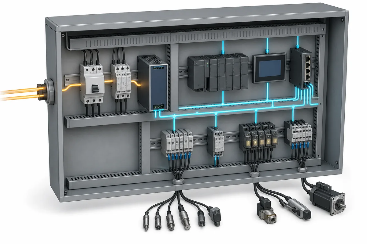
Separate continuous demand from temporary peak demand. Then check the manufacturer’s overload or power-reserve behavior, including how long additional current is available and what happens when the limit is exceeded. Do not assume that every supply can support the same startup profile. A high nameplate rating cannot compensate for incompatible current limiting, foldback, hiccup, or shutdown behavior.
Reserve capacity should be intentional. It can support normal variation, component tolerance, future additions, and dynamic loads, but excessive oversizing may increase cost and cabinet space without solving a defined problem. Document which loads can operate simultaneously and validate the most demanding operating state.
Verify the Input Source and Disturbance Environment
The available input must remain inside the power supply’s supported range under normal and abnormal plant conditions. Confirm nominal voltage, frequency where applicable, phase arrangement, protective devices, wiring method, and the behavior expected during short dips or interruptions. Machines exported to multiple regions may require a broader input strategy, but the exact range must come from verified product data.
Industrial distribution can expose equipment to disturbances created by contactors, drives, motors, transformers, heaters, and long cable runs. The finished system may need to address surge, electrical fast transients, conducted noise, and electrostatic discharge. A compliance mark on an individual PSU does not automatically prove that the assembled machine or cabinet will pass its required tests. Earthing, cable layout, filters, enclosure construction, and load behavior affect the result.
Hold-up performance also matters when a controller must ride through a brief input disturbance. If process continuity requires more energy storage than the AC-DC supply provides, the architecture may need a DC UPS, redundancy module, buffer module, or controlled shutdown strategy. Treat these as system decisions rather than assumptions about the base supply.
Account for Temperature, Airflow, and Altitude
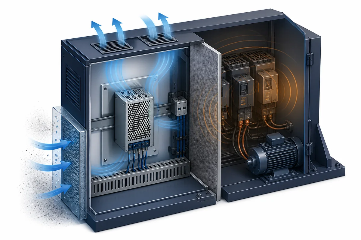
Power ratings are valid only under specified environmental conditions. Heat generated by conversion losses joins the heat from PLCs, drives, contactors, and other cabinet devices. In a sealed or crowded enclosure, the air surrounding the supply can be substantially warmer than the room outside.
Check the allowed mounting orientation, required clearances, cooling method, and temperature derating curve for the exact unit. Natural-convection designs need unobstructed airflow paths, while fan-cooled products need suitable intake and exhaust space. Installing a supply next to a major heat source or blocking its ventilation can reduce available output and component life.
Altitude can also require derating because lower air density reduces convective cooling and may affect insulation requirements. Never copy a temperature or altitude limit from a similar product. Use the documented operating envelope of the selected supply and evaluate the temperature at the supply’s actual inlet or reference point.
Control EMI, Grounding, and Wiring Layout
Good power conversion cannot overcome poor installation practice. Keep high-energy switching conductors away from low-level analog, sensor, and communication wiring. Route AC input and DC output deliberately, minimize unnecessary loop area, and follow the equipment manufacturer’s protective-earth and chassis-bonding instructions.
Long DC runs introduce voltage drop and can carry noise between cabinet zones. Conductor size, terminal quality, branch protection, and remote-sense arrangements—when supported—must be evaluated as part of the distribution design. Remote sense should never be assumed; its wiring and failure behavior depend on the specific supply.
Loads that create strong transients may benefit from separation, local suppression, dedicated branches, or additional conversion stages. The correct approach depends on the load and system requirements. Validate noise performance with the production wiring layout because a bench setup may not reproduce the cable lengths, grounding paths, or adjacent switching equipment found in the machine.
Match Protection and Reliability to the Failure Model
Industrial supplies commonly provide protection against conditions such as overvoltage, overcurrent, overtemperature, and short circuit, but the thresholds and recovery behavior vary. Determine whether a fault causes current limiting, repeated restart attempts, a latched shutdown, or another response. That behavior must be compatible with both the load and the machine’s safety and recovery logic.
Where loss of one supply cannot be tolerated, consider whether the system requires redundant supplies, separated input feeds, output decoupling, health monitoring, or an energy-storage stage. Redundancy is not created merely by placing two units in the same enclosure. The distribution and control architecture must prevent one failure from disabling the remaining path.
Reliability planning should also cover replacement access, terminal identification, spare-part control, and commissioning records. A service technician should be able to confirm the correct voltage setting, wiring, protection, and grounding before a replacement is energized.
A Practical Industrial Power Supply Selection Process
- Define the environment. Record input source, enclosure, ambient temperature, altitude, contamination, vibration, and applicable equipment requirements.
- Map the loads. List continuous current, startup demand, switching peaks, sequencing, and allowed voltage variation.
- Select the mechanical format. Choose DIN rail, enclosed chassis, or open frame according to integration, protection, cooling, and service needs.
- Check electrical behavior. Verify input range, output regulation, dynamic response, overload behavior, protection, and hold-up needs using supported data.
- Apply environmental derating. Confirm available output at the actual temperature, mounting orientation, airflow, and altitude.
- Review installation details. Validate earthing, conductor sizing, terminal access, branch protection, cable segregation, and enclosure ventilation.
- Test the complete system. Exercise startup, worst-case load combinations, disturbances, faults, recovery, and thermal steady state in the production configuration.
Powernexu’s verified industrial power supply catalog provides a starting point for comparing available formats and models. Shortlisting should always be followed by a model-specific review against the target machine, load, environment, and compliance plan.
Make the Power Supply Part of the Machine Design
A dependable industrial power system results from coordinated electrical and mechanical decisions. The supply must fit the enclosure, start the real load, tolerate the installation environment, coexist with noisy equipment, and respond predictably to faults. These requirements cannot be reduced to a single wattage value.
Document the operating envelope, validate the production configuration, and preserve the assumptions used during selection. That process turns an industrial power supply from a catalog component into a controlled part of the equipment’s reliability strategy.