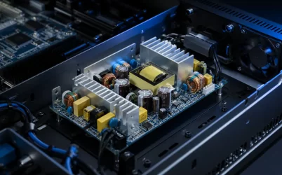
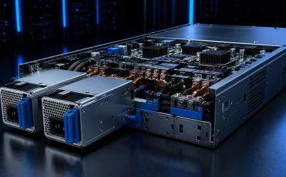
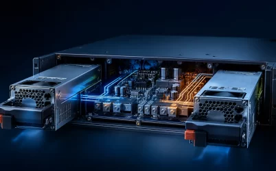
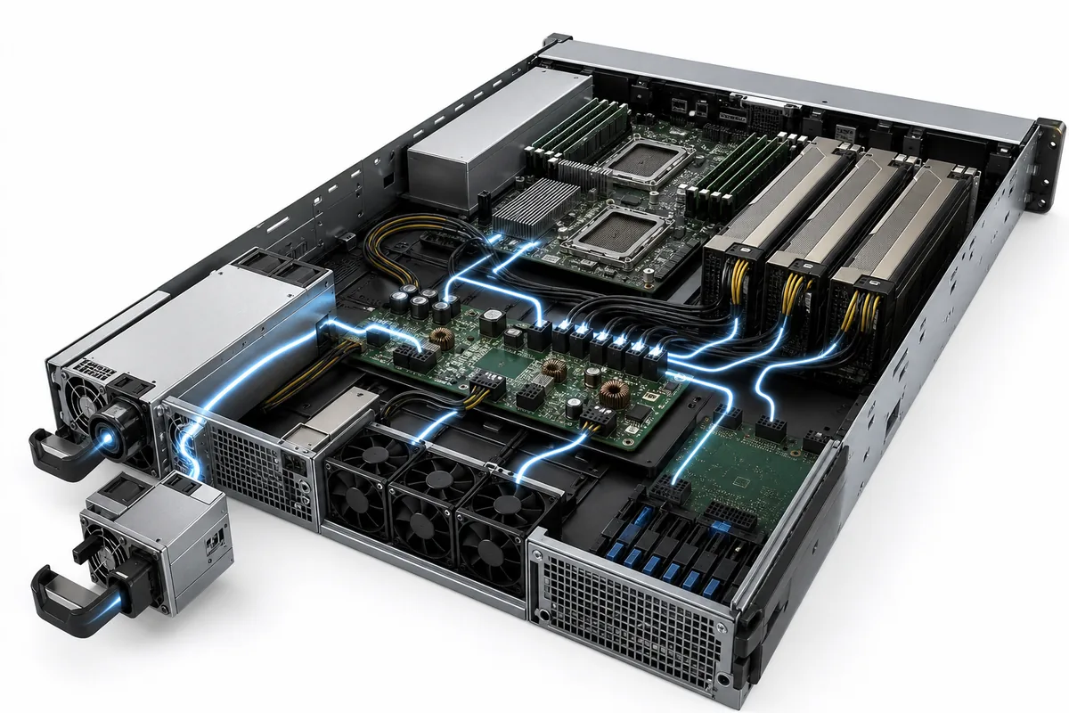
A CRPS power distribution board is the electrical and mechanical bridge between removable Common Redundant Power Supply modules and the server loads. It accepts power from one or more CRPS units, combines or isolates their outputs as the architecture requires, and routes the DC bus, standby power, control signals, and monitoring connections toward the motherboard, accelerators, storage, and fans. Selecting the CRPS modules alone is therefore insufficient: the PDB must match their output voltage, connector system, current capacity, redundancy mode, hot-swap behavior, airflow, management interface, and chassis geometry. A mismatch can prevent startup, defeat redundancy, overheat a current path, or leave the BMC unable to identify and control the power subsystem.
How CRPS Modules and the PDB Divide the Work
The CRPS module performs AC-DC conversion and typically contains its own input protection, power-factor-correction stage, isolation, output regulation, cooling fan, and internal protection functions. The PDB does not simply act as a passive adapter. Depending on the platform, it may provide high-current interconnection, output ORing or coordination, hot-swap support, standby distribution, current sensing, protection, connectors for multiple loads, and signal routing between the supplies and the system controller.
| Subsystem Element | Primary Responsibility | Selection Consequence |
|---|---|---|
| CRPS module | Convert input power into the specified regulated DC output | Match input source, output bus, capacity, cooling, and electrical interface |
| Power distribution board | Receive, combine, protect, monitor, and route power to server loads | Match module connector, current, redundancy method, signals, and chassis |
| Motherboard and load boards | Convert the distributed bus into point-of-load rails | Confirm connector pinout, sequencing, transient demand, and cable losses |
| BMC or system controller | Monitor status, inventory, faults, and operating data | Verify supported management protocol, addressing, and control behavior |
The practical implication is that “CRPS compatible” is not a complete compatibility statement. Common mechanical families can reduce design variation, but a platform still has to confirm the exact output architecture, mating connector, signal definition, firmware expectations, and permitted operating modes. The correct unit is the one validated with the specific PDB and server design.
Redundancy Is a Capacity Rule, Not a Module Count
Two installed power supplies do not automatically double the server’s usable power. In a 1+1 redundant configuration, either module must support the required load after the other module fails or is removed. During normal operation the modules may share current, but the design capacity is limited by what remains after the defined failure. A 2+0 configuration can use the combined capacity of two modules, but it does not preserve operation after losing one.
Consider a hypothetical 12V server bus with a maximum sustained load of 1,200W. The bus current is:
1,200W ÷ 12V = 100A
If the platform uses two 1,600W CRPS modules in 1+1 redundancy, each module carries approximately 600W during ideal balanced operation. After one module is removed, the surviving module must deliver the full 1,200W, which is 75% of its 1,600W rating. The PDB, connector, copper paths, and downstream cabling must still carry approximately 100A continuously, plus the validated transient and design margin. The available redundant capacity is 1,600W, not 3,200W.
This example also explains why voltage architecture changes PDB design. Delivering the same 1,200W at a hypothetical 54V bus requires about 22.2A before downstream conversion. Higher distribution voltage can reduce current and conductor loss for the same power, but it requires compatible CRPS modules, PDB architecture, connectors, insulation, downstream converters, and controls. It is a system decision, not a drop-in voltage substitution.
Current Sharing and Transient Response Must Be Coordinated
Current sharing means the online CRPS modules divide the load without one module being forced to carry a disproportionate share. In plain language, it keeps a pair of supplies from fighting each other or overheating one unit while the other remains lightly loaded. For the engineer, this means the share bus, output path impedance, connector resistance, PDB layout, and supported control method must work together.
Perfect equality is not the objective; operation within the specified sharing limits is. Small differences in module output voltage or path resistance can shift substantial current at a low-voltage, high-current bus. Validate sharing at low, medium, and high load, across temperature, with the approved module population and with realistic connector aging assumptions.
Transient response is the subsystem’s ability to keep the DC bus within its allowed range when load changes quickly. AI accelerators, processors, fans, and storage devices can change demand faster than a monitoring dashboard suggests. The CRPS control loop, PDB impedance, bulk capacitance, connector inductance, cable length, and point-of-load converters all contribute. Selection therefore requires a platform-level load-step test, not just confirmation that average wattage is below the module rating.
High-Current PDB Layout Determines Loss and Temperature
At high current, small resistance becomes meaningful heat. The relationship is P = I²R, so doubling current increases resistive heating by a factor of four when resistance is unchanged. As a hypothetical illustration, a distribution path with 0.5 milliohm resistance carrying 100A dissipates:
100A × 100A × 0.0005Ω = 5W
That loss can be concentrated in a connector, copper joint, bus structure, or current-sense element. It also creates voltage drop at the load. This is why a PDB’s current rating cannot be inferred from board size or connector appearance. Copper weight and geometry, busbars, vias, terminals, contact resistance, thermal spreading, airflow, and allowable temperature rise must be verified from supported design data and system testing.
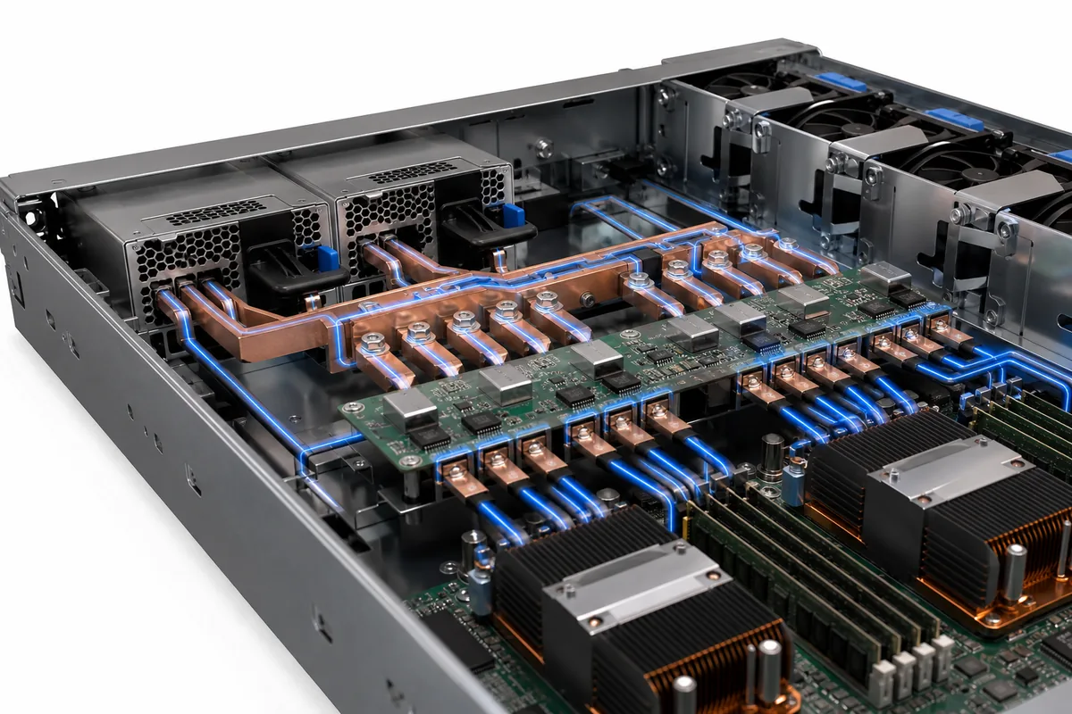
Measure temperature at the highest-resistance and lowest-airflow locations under maximum continuous load and the worst supported ambient condition. Include the effect of one-module operation, because current may concentrate through one input connector and a different section of the PDB after a module failure. A design that runs cool during balanced sharing may have a much hotter failure-state current path.
Hot Swap Requires Controlled Electrical Sequencing
Hot swap means a module can be inserted or removed while the system remains powered, but the physical handle is only the visible part of the function. Contacts must mate in the intended sequence, inrush into the live bus must be controlled, output ORing must prevent reverse energy flow, and control signals must change state without producing an unsafe or ambiguous condition.
For the integrator, the selection consequence is clear: never evaluate the CRPS and PDB hot-swap behavior independently. Test insertion, extraction, slow or partial insertion, input interruption, failed-module removal, and replacement under realistic load. Confirm that the surviving path remains within its electrical and thermal limits and that the BMC reports the event correctly.
Connector wear and service handling also matter. The chassis must guide the module into the PDB without side loading or misalignment. Latches, ejectors, card guides, and rear connector support should prevent operators from using the electrical connector as a mechanical alignment tool.
Management Signals Must Match the Platform
CRPS telemetry can expose useful operating information such as input status, output condition, temperature, fan state, warnings, and faults, but the exact data and control behavior depend on the supported specification and implementation. PMBus is a management interface, not proof of universal interoperability. Two devices may both support PMBus while differing in command set, addresses, scaling, manufacturer-specific data, or platform initialization.
The BMC design should define which signals are required for boot, fault handling, power capping, inventory, service alerts, and firmware policy. The PDB must route or multiplex those signals correctly for every installed module. Verify behavior when one supply is absent, when addresses conflict, when communication is lost, and when module firmware revisions differ within the combinations permitted by the platform.
Mechanical Fit and Airflow Are Electrical Requirements
CRPS module length, height, handle geometry, connector position, insertion depth, and airflow direction must match the chassis and PDB. A connector that appears electrically suitable can still fail to mate correctly because of mechanical keying, datum differences, or unsupported module length. Use controlled drawings and approved samples rather than nominal form-factor names alone.
Airflow through the module and across the PDB must also remain continuous. The PDB, bus structures, cable bundles, and nearby accelerators can obstruct the server’s front-to-rear cooling path. Fan control should account for module state and system impedance. Validate module exhaust temperature, PDB hotspots, connector temperature, and downstream inlet temperature with the final air duct and chassis covers installed.
| Application | Main PDB Concern | Validation Priority |
|---|---|---|
| AI/GPU server | High current and rapid load change | Transient response, connector temperature, and failure-state capacity |
| Storage server | Drive startup and multiple distribution branches | Startup sequencing, voltage drop, and branch protection |
| Telecom or edge system | Compact space and limited cooling margin | Input architecture, airflow, service access, and thermal derating |
| Enterprise server | Availability and field replacement | 1+1 redundancy, hot swap, telemetry, and approved module combinations |
Selection and Validation Checklist
- Define the maximum sustained, startup, and transient load at the distribution bus.
- Choose the required operating mode: 1+0, 1+1, N+1, or combined nonredundant capacity.
- Confirm CRPS output voltage, connector family, pin definition, standby power, share method, and management interface.
- Verify the PDB’s continuous and transient current capacity for normal and failure-state paths.
- Check downstream connector ratings, cable loss, branch protection, grounding, and point-of-load requirements.
- Validate mechanical docking, module retention, hot-swap sequencing, and service access.
- Test current sharing, load steps, module removal, insertion, faults, telemetry, and thermal performance in the finished chassis.
Once the platform requirements are fixed, Powernexu’s verified CRPS power supply category can be used to compare available module families. The PDB and CRPS should then be reviewed as one qualified power subsystem rather than purchased from headline wattage alone.
Frequently Asked Questions
Does a CRPS power distribution board convert voltage?
Not necessarily. Many PDBs primarily combine, protect, monitor, and route the CRPS output bus. Some platforms include additional conversion elsewhere in the distribution architecture. The exact function must be confirmed from the specific design documentation.
Can any CRPS module work with any CRPS PDB?
No. Mechanical form factor alone does not guarantee compatibility. Output voltage, power and current limits, connector and pin definition, management signals, airflow, firmware expectations, and approved operating modes must all match.
Does installing two CRPS modules double available server power?
Only in a combined-capacity, nonredundant mode supported by the platform. In 1+1 redundancy, either module must support the required load after the other fails, so redundant capacity is normally limited by one module’s supported output under the actual conditions.
Why can the PDB overheat when the CRPS modules are within rating?
The modules and PDB have separate electrical and thermal limits. High contact resistance, concentrated current, insufficient copper, obstructed airflow, or a failure-state path can overheat the distribution board even while each supply remains within its own output rating.
A reliable CRPS subsystem is achieved when conversion, distribution, redundancy, mechanics, cooling, and management operate as one validated design. The decisive question is not whether the parts are individually powerful enough, but whether the complete path remains electrically stable, thermally controlled, serviceable, and observable after the failures the platform is expected to survive.