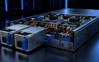
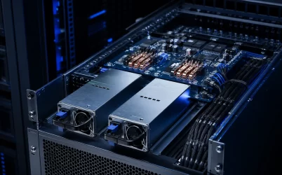
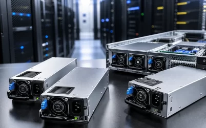
A redundant power supply uses two or more power sources so a critical load can remain powered after a defined supply or input-path failure. The phrase does not describe one universal circuit: it may refer to dual hot-swap server modules, parallel industrial DIN-rail supplies with a redundancy module, N+1 telecom rectifiers, or separate A/B facility feeds. A sound design begins by defining the failure it must survive, then verifies capacity, isolation, wiring, thermal behavior, monitoring, and maintenance as one system.
Quick Answer
A redundant power supply is appropriate when interruption from a single power-source failure is unacceptable. For true 1+1 redundancy, either supply must carry the entire validated load after the other fails; two supplies that are both required for normal capacity are operating as combined power, not redundant power. Check the complete path: independent inputs where needed, compatible supplies, output isolation or an approved power distribution board, failure-state capacity, current sharing, airflow, alarms, and hot-swap procedure. The correct architecture depends on the failure domain—PSU module, branch circuit, PDU, utility feed, or a wider facility event—that the equipment must tolerate.
What a Redundant Power System Actually Protects
Redundancy is a system property rather than a label on an individual PSU. Adding a second unit can protect against a failed converter, but it may not protect against an upstream breaker trip if both inputs use the same branch circuit. Likewise, two independent AC feeds can still converge at a single output connector, redundancy module, backplane, or cable that becomes a common point of failure.
Define the intended failure domain before selecting hardware. Typical design targets include one failed or removed PSU, loss of one AC or DC feed, one open protective device, one failed output-isolation path, or scheduled replacement while the load remains online. Wider events—such as a transfer-switch fault or loss of a complete facility source—usually require coordination with UPS, generator, rack PDU, battery, and distribution design.
The practical test is simple: after the specified fault occurs, does a complete healthy path remain from the source to every essential load, and can that path support the resulting electrical and thermal conditions?
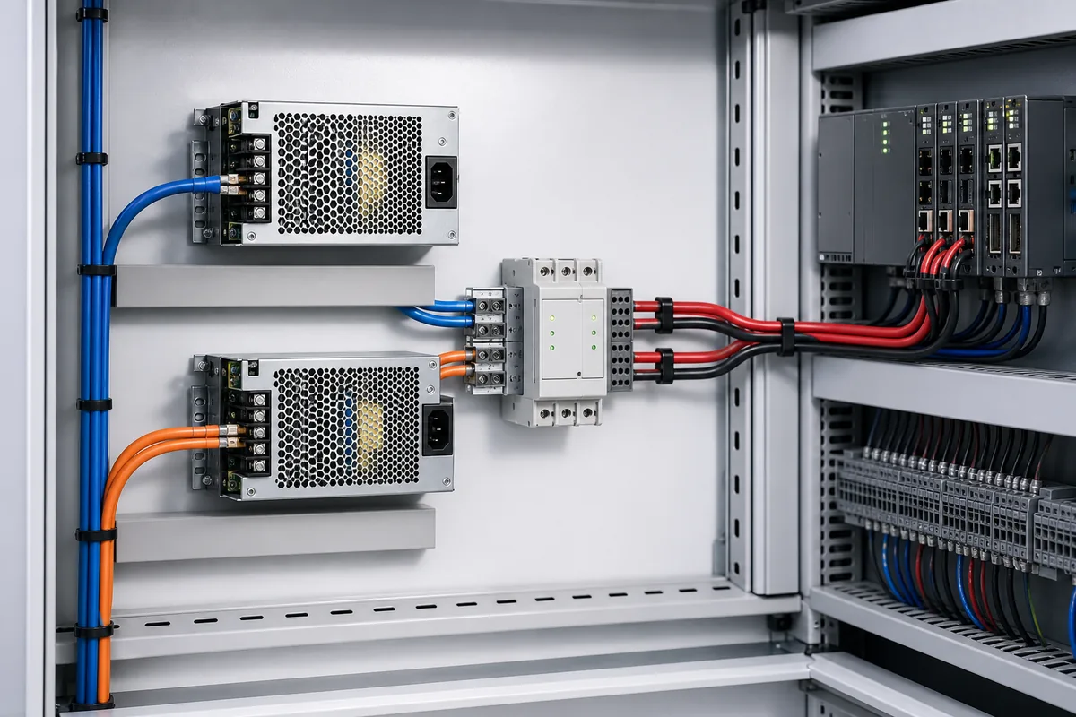
Two supplies provide useful redundancy only when the surviving source, isolation path, distribution, and wiring can carry the required load.
How Common Redundancy Architectures Differ
| Architecture | Normal Operation | Capacity After One Failure | Typical Use |
|---|---|---|---|
| 1+1 | Two supplies installed; one or both may deliver power | One supply must support the full required load | Servers, storage, controls, network equipment |
| N+1 | N modules support the load plus one additional module | The remaining N modules support the required load | Modular rectifiers, larger chassis, scalable systems |
| N+N | Two complete capacity groups or paths | Either group supports the required load | High-availability A/B power architectures |
| Combined power | Multiple supplies are required to meet demand | Capacity may be insufficient after one fails | High-power operation where redundancy is not required |
These terms describe capacity intent, but implementation varies. A 1+1 platform may actively share current between both PSUs, keep one in a low-power standby state, or use platform management to change operating modes. Do not assume that two installed modules automatically mean 1+1 operation. Some server platforms change from redundant to combined operation when load exceeds the rating available from one module.
Parallel operation also requires care. Supplies designed only for current sharing may not provide the reverse-current isolation needed for redundancy. Industrial systems commonly use supplies with an approved redundant function or an external diode- or MOSFET-based redundancy module. Use the connection method, conductor sizing, voltage adjustment, and compatible supply combinations defined by the relevant manufacturer.
Size Capacity for the Failure State
Normal-load arithmetic is not enough. Capacity must be checked at the input voltage, ambient temperature, airflow, altitude, transient demand, and redundancy mode expected in service. Derating and platform-specific limits can reduce usable output below the nameplate value.
Consider a hypothetical 24 V industrial control system with a measured worst-case continuous load of 480 W. The corresponding output current is:
480 W ÷ 24 V = 20 A
For 1+1 redundancy, each supply and each surviving output path must support at least the required 20 A under the validated operating conditions. If two 24 V, 600 W supplies are used, each has a nominal rating of 25 A, so failure-state utilization would be 20 A ÷ 25 A = 80%. That result is only a starting point. The engineer must still verify peak loads, start-up current, ambient derating, cable voltage drop, protection coordination, redundancy-module losses, and whether 80% utilization leaves the required project margin.
For N+1 systems, apply the same principle to the remaining N modules. If the load rises beyond the capacity that remains after one module is lost, the installation may continue to run in a nonredundant mode, throttle, shed load, or shut down depending on the platform. The expected response must be documented and tested.
Separate Input Paths to Reduce Common-Mode Risk
Two PSUs connected to one outlet strip protect against some internal PSU failures but not loss of that strip, cord, breaker, or upstream feed. Where the availability target requires input-path resilience, connect the supplies to appropriately designed A and B paths. Those paths may include separate rack PDUs, branch circuits, UPS outputs, or facility sources, subject to the site electrical design.
Independence should be evaluated rather than assumed. Two receptacles can share a breaker; two rack PDUs can share an upstream panel; and two utility feeds can converge at a single transfer device. Maintenance procedures also matter: an A/B architecture offers limited value if both sides are de-energized during the same service activity.
For DC installations, the equivalent questions apply to battery strings, rectifier shelves, protective devices, disconnects, grounding, and distribution buswork. The desired availability level determines how far upstream duplicated paths should extend.
Isolation, Distribution, and Current Sharing
When multiple outputs feed a common DC bus, one source should not backfeed a failed or unpowered source unless the design explicitly permits it. Isolation can be integrated into a PSU, implemented on a server power distribution board, or added through a redundancy module. Diode-based isolation is straightforward but introduces forward-voltage loss and heat. MOSFET-based “ideal diode” approaches can reduce loss, although device ratings, control behavior, fault response, and qualification still need verification.
Current sharing keeps operating supplies from being unintentionally overloaded and can improve thermal balance. It may be active through dedicated share signals or controlled digitally, or passive through closely matched output voltage and path impedance. Exact behavior is product-specific. Mixing different models, firmware revisions, output setpoints, or cable resistances can create unequal loading and may be unsupported even when nominal voltage ratings match.
The distribution path is part of the power system. Connectors, backplanes, busbars, fuses, circuit breakers, PCB copper, and wiring must carry normal and failure-state current without excessive temperature rise or voltage drop. For server designs, review the CRPS power distribution board as a coordinated interface rather than treating the PSU wattage as the only selection variable.
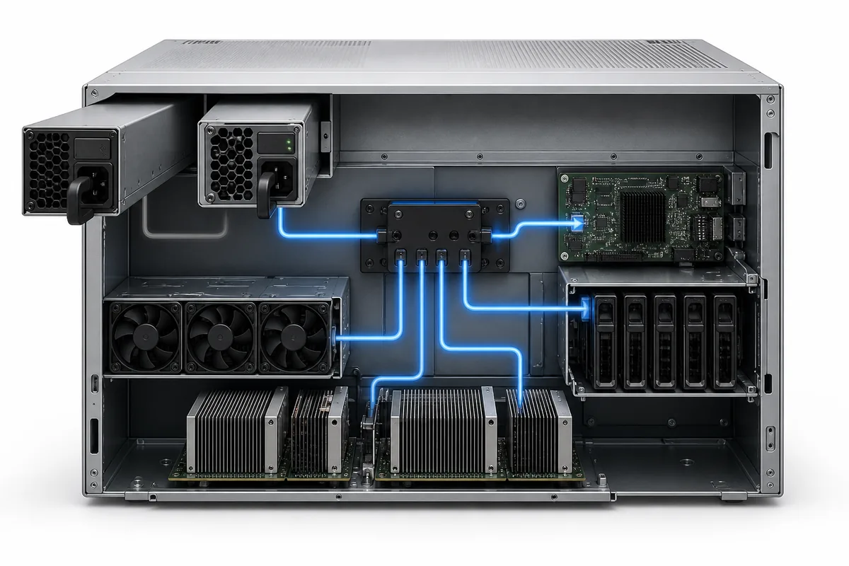
A controlled failure test should confirm that the healthy supply takes the required load without unacceptable output interruption or overheating.
Thermal Efficiency and Maintenance Trade-Offs
Redundancy adds equipment, conversion paths, and sometimes isolation losses. In active load-sharing mode, two supplies may operate at a lower percentage of rating than one supply would. Depending on the efficiency curve, this can improve or reduce total efficiency. Some managed platforms therefore use cold-redundant or standby modes, keeping only the required number of modules active and bringing another online after a fault or load increase.
Efficiency strategy must not compromise the required transition performance. Confirm how quickly the standby module becomes active, what output deviation occurs during transfer, and how the load responds. Thermal validation should include the failed-module condition because the surviving PSU may run hotter while system airflow changes due to a stopped fan or removed module.
Hot swap means a module can be replaced without intentionally shutting down the load when the platform is in a supported redundant state. It does not mean every PSU can be removed under every load condition. Before service, confirm that redundancy is healthy, identify the failed module correctly, verify the remaining capacity, follow the platform procedure, and monitor alarms after replacement.
Choose the Architecture for the Application
| Scenario | Primary Decision Factors | What to Verify |
|---|---|---|
| Rack server or storage | 1+1 capacity, hot swap, chassis and management compatibility | Supported PSU pair, single-module load limit, A/B feeds, airflow, BMC status |
| Industrial control cabinet | 24/48 V load continuity, isolation, DIN-rail space, ambient conditions | Redundancy module rating, derating, surge/start-up load, diagnostics, wiring |
| Telecom or distributed DC | N+1 scalability, battery integration, maintainability | Rectifier sharing, bus protection, alarm interfaces, remaining capacity |
| AI/GPU or other high-current system | Peak demand, transient response, cooling, distribution loss | Failure-state power budget, connector/busbar rating, throttling behavior, feed capacity |
For a deeper server-specific workflow, see the server redundant power supply guide. For industrial or telecom equipment, the same system-level reasoning applies, but mechanical interfaces, voltage classes, environmental standards, and monitoring protocols may differ substantially.
Validation Checklist Before Deployment
- Define the exact single failure or maintenance event the system must survive.
- Measure or calculate worst-case continuous and transient load.
- Apply input-voltage, temperature, altitude, airflow, and other required derating.
- Confirm remaining capacity after one PSU or one path is unavailable.
- Verify manufacturer-supported supply combinations, sharing, and hot-swap behavior.
- Check output isolation, backfeed protection, distribution, connectors, and conductor ratings.
- Map A/B inputs to genuinely independent upstream paths where required.
- Confirm alarms, telemetry, event logging, and remote management behavior.
- Test a controlled failure and restoration while monitoring voltage, current, temperature, and application continuity.
- Document replacement steps and periodically retest the redundancy state.
Frequently Asked Questions
Is a dual power supply automatically redundant?
No. It is redundant only when the remaining supply and complete surviving path can support the required load after the defined failure. If both supplies are needed to meet demand, the arrangement is combined power rather than 1+1 redundancy.
What is the difference between redundant and parallel power supplies?
Parallel supplies share load or increase output capacity. A redundant arrangement also preserves the required output after one source fails and normally includes suitable isolation or backfeed protection. Some products support both functions, but parallel capability alone does not prove redundancy.
Do redundant power supplies need separate AC feeds?
Separate feeds are needed when the design must tolerate loss of an upstream power path. Two PSUs on one feed can still protect against an internal PSU fault, but they share the feed as a common failure point. The availability objective determines how independent the inputs must be.
Can different power supply models be used together?
Only when the equipment and PSU manufacturers explicitly support the combination. Matching voltage and wattage is not sufficient; sharing control, firmware, pinout, timing, mechanical fit, thermal behavior, and management communication can differ. Identical or formally qualified modules are the safer default.
A dependable redundant power supply design is therefore built from a verified power path, not from a second box alone. Define the fault, size the survivor, remove avoidable common points, validate distribution and thermal behavior, and test the actual transition. That process produces a defensible architecture for servers, industrial controls, telecom systems, and other equipment where power continuity matters.