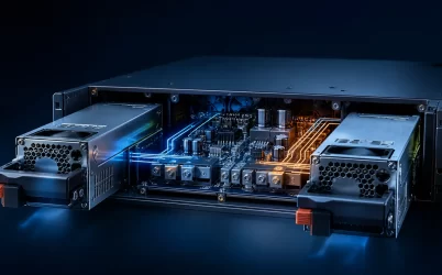
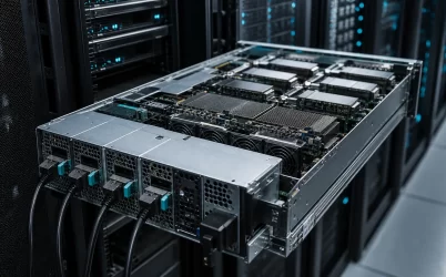
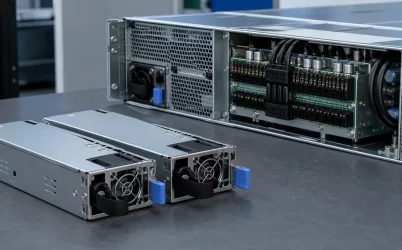
A server power supply converts facility AC or DC input into regulated power that a server can distribute safely to processors, memory, storage, accelerators, fans, and standby circuits. In many enterprise platforms, it is also a managed, hot-swappable subsystem that reports status to the baseboard management controller (BMC) and cooperates with other modules during redundant operation. Understanding the full path—from rack power distribution to the PSU, power-distribution board (PDB), board-level converters, and workload—is essential because wattage alone does not establish compatibility, resilience, or performance.
Quick answer: what does a server PSU do?
A server PSU performs four related jobs. It converts the available input into the DC architecture required by the platform, regulates that output as load changes, isolates and protects the server from defined electrical faults, and may provide telemetry and control through a management interface. In redundant systems, multiple modules can share load or provide reserve capacity according to the server’s supported operating mode. The correct unit must therefore match the chassis, mating connector, PDB, output architecture, input range, cooling direction, firmware expectations, and protected load—not just the nominal power rating.
The electrical path from the rack to silicon
Power conversion in a server occurs in stages. The rack power-distribution unit supplies an approved input through the cord and inlet. Inside an AC-input PSU, filtering, rectification, power-factor correction, isolation, switching conversion, and output regulation produce the specified DC output. The exact topology is model-specific, but the engineering objective is consistent: deliver controlled power while meeting the applicable safety, electromagnetic compatibility, thermal, and transient requirements.
The PSU output then reaches a PDB, backplane, cable harness, or busbar. That distribution layer carries high current to the motherboard and other loads, may combine redundant modules, and often carries presence, status, or management signals. On the motherboard and accelerator boards, voltage-regulator modules convert the intermediate bus into lower voltages near the devices that consume them.
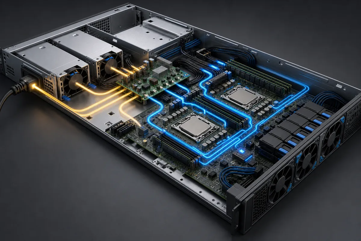
This layered structure explains why replacing a PSU is not equivalent to replacing a generic energy source. The connector, output voltage, standby rail, current capability, timing, control signals, and management behavior must agree with the rest of the platform. A mechanically similar module may still be incompatible with the PDB or BMC.
Distribution architecture defines the integration problem
Server platforms do not all use the same intermediate bus. Many conventional CRPS designs distribute a main 12 V output and perform point-of-load conversion on the boards. Higher-voltage rack or system architectures may distribute 48 V or a nearby nominal voltage to reduce current for a given power level, then convert closer to the load. Some specialized platforms use other voltages or multiple direct output rails.
| Architecture choice | Engineering effect | What must be verified |
|---|---|---|
| 12 V intermediate bus | High current at elevated server power, with conversion near processors and other loads | PDB, connector, copper, cable, and VRM current capability |
| Higher-voltage DC bus | Lower distribution current for the same power, with an added conversion stage near the load | Busbar and connector ratings, DC-DC topology, protection, isolation, and service procedure |
| Multiple direct rails | PSU supplies several system voltages rather than one main intermediate bus | Rail limits, sequencing, regulation, connector mapping, and load allocation |
For example, a hypothetical 2,400 W load draws 200 A from a 12 V bus before allowing for distribution and conversion losses:
2,400 W ÷ 12 V = 200 A.
The same idealized power at 48 V corresponds to 50 A:
2,400 W ÷ 48 V = 50 A.
This arithmetic does not make one architecture universally better. Higher voltage can reduce current and associated conductor losses, but it changes insulation, connector, protection, conversion, and service requirements. A 12 V architecture may remain appropriate where a qualified ecosystem already supports the required current and power density. Engineers should make the decision at platform level rather than selecting the PSU independently.
Redundancy depends on capacity and upstream separation
Module count does not by itself define redundancy. In a 1+1 configuration, one PSU can normally support the protected server load while the second provides redundant capacity. In a supported 2+0 mode, both modules contribute to a load that exceeds one module’s capability, so the system no longer has PSU-level power redundancy at that operating point. Intel documents this conditional distinction for server systems that automatically choose between 1+1 and 2+0 operation based on load.
Current sharing is the mechanism by which active modules divide load within the tolerances defined for the platform. It matters because poor sharing can thermally overstress one module or the common distribution path even when the arithmetic total appears sufficient. Hot swap is a separate property: it describes whether a module can be replaced while the supported system remains energized. The server, PDB, connector, firmware, and operating procedure must all support the event.
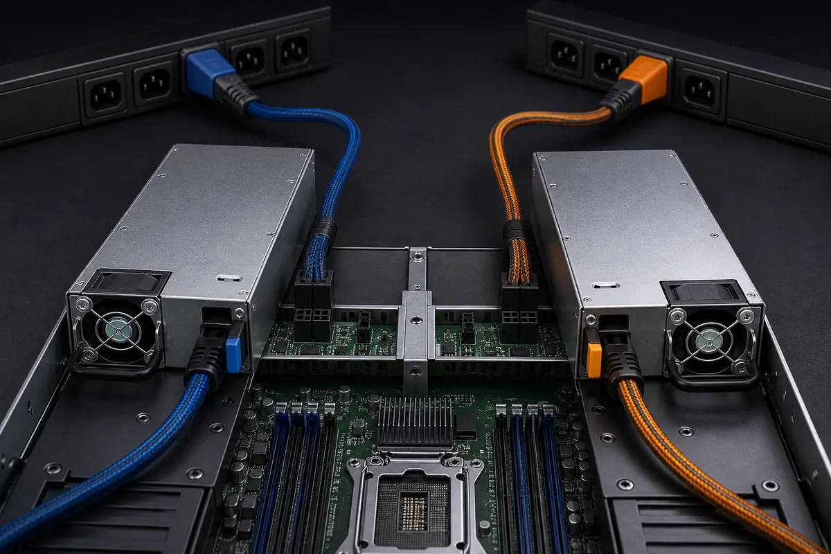
Resilience also extends upstream. Connecting two PSUs to the same rack PDU leaves that PDU and its branch circuit as common failure points. Where the availability design requires independent paths, the cords must reach appropriately separated rack PDUs and upstream sources. The necessary topology depends on the server and facility design; dense AI systems may use N+1, N+N, or other manufacturer-defined arrangements rather than a simple two-module pattern.
For compact platforms, the discussion in 1U server PSU compatibility and sizing covers additional bay, airflow, and blind-mate constraints.
Dynamic workloads expose weaknesses that average power hides
Server loads can change quickly as processors enter boost states, accelerators begin synchronized work, drives start, or fans respond to a thermal event. Average facility telemetry may be useful for energy planning, but it may miss short events that challenge regulation, PDB voltage drop, connector temperature, or the PSU’s transient response.
Consider a hypothetical platform with an 820 W measured sustained DC demand and a validated 180 W short-duration workload step. If the engineering team also requires 10% capacity margin on the sustained value, the two checks are:
Sustained requirement: 820 W × 1.10 = 902 W.
Observed short-duration level: 820 W + 180 W = 1,000 W.
The selection implication is not simply “buy a 1,000 W PSU.” The team must confirm that a candidate module and the complete server power path can support the defined transient duration, input voltage, temperature, altitude, airflow, and redundancy state. A nameplate rating does not describe every dynamic condition. If two modules are intended to provide 1+1 redundancy, the required behavior must also be validated with one module unavailable.
Thermal behavior belongs in the same review. Conversion loss becomes heat, while 1U and high-density chassis offer limited airflow area. Fan direction, pressure resistance, inlet temperature, altitude derating, dust assumptions, and cable placement can change available output or component temperature. Efficiency should be evaluated across the expected load range, not from a single peak figure generalized to all conditions.
Digital management makes power observable
PMBus is an open-standard digital power-management protocol used to communicate with power converters and related components. In a supported server implementation, the BMC may use it to obtain model-specific information such as input or output measurements, temperature, fan data, warnings, faults, and inventory. The exact command set, accuracy, update rate, addressing, and control permissions vary by module and platform.
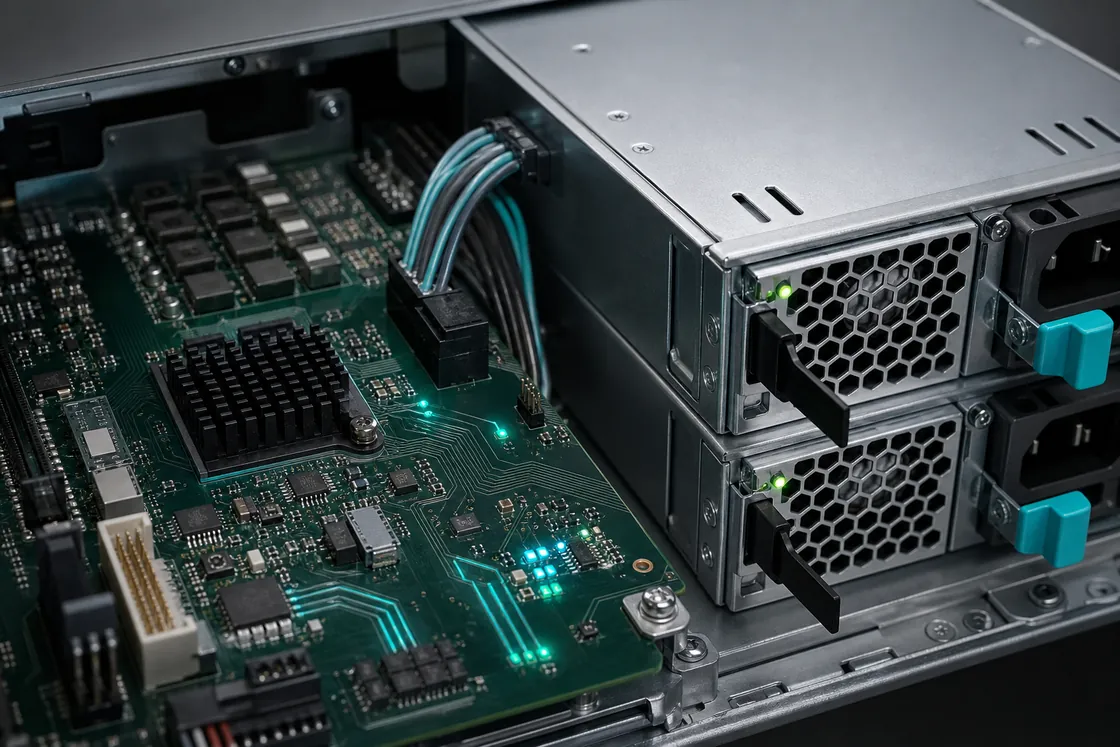
Telemetry is useful only when the system interprets it correctly. An integrator should verify device addressing, supported commands, scaling and data formats, sensor accuracy, warning thresholds, event logging, firmware compatibility, and behavior when communication is lost. PMBus capability does not automatically make any two PSUs interchangeable, and an I2C-compatible electrical interface alone does not prove that the host and module implement the same application behavior.
Management data can support maintenance and capacity decisions. Rising fan speed at the same load may indicate increasing inlet temperature or flow restriction; input-power data can help compare operating points; and fault history can distinguish a removed module from an electrical trip. These are diagnostic signals rather than guarantees, so important protection and availability decisions should not depend on one unvalidated sensor.
Qualification turns component specifications into system evidence
A defensible server power design is verified on the intended platform. Begin with the server configuration and approved electrical architecture, then connect each specification to a system test.
- Define the load envelope. Record processor, accelerator, memory, storage, NIC, fan, and peripheral configurations, including permitted future options and startup states.
- Validate the physical interface. Check module dimensions, insertion depth, guides, latch, connector alignment, service clearance, and airflow direction.
- Audit the distribution path. Confirm output rails, standby power, PDB or busbar ratings, connector temperature rise, copper capacity, protection devices, and grounding.
- Exercise dynamic conditions. Test sustained load, representative transients, startup, maximum fan operation, and recovery from supported fault events.
- Prove the redundancy model. Remove input from each path and replace a module according to the approved procedure while monitoring load, voltage, thermals, and event logs.
- Check management integration. Verify identification, telemetry, warnings, fault reporting, addressing, and firmware behavior through the BMC.
- Review the deployment environment. Include rack PDU capacity, independent feeds where required, inlet temperature, altitude, cord ratings, compliance markets, and maintenance access.
Powernexu’s server PSU selection workflow provides a complementary procurement-focused checklist. For a model-specific example, the CRPS1300N2 product page documents one available CRPS configuration; its ratings and interfaces should be treated as specific to that model and verified against the target platform.
Can a higher-wattage PSU replace an approved lower-wattage model?
Only when the server or chassis documentation supports the exact replacement. Higher nominal capacity does not establish mechanical, connector, airflow, management, firmware, or current-sharing compatibility.
Does hot swap mean the server has redundant power?
No. Hot swap describes supported replacement while the system is energized. Redundancy requires sufficient remaining capacity and an architecture that continues operating after the defined failure or removal event.
Why can two equal PSUs still lose redundancy?
If the server load exceeds what one module can support under the specified conditions, both modules may be required. The platform may then operate in a combined-power mode rather than a redundant mode.
What should a buyer request from a supplier?
Request controlled mechanical drawings, input and output specifications, derating information, connector and communication documentation, efficiency and compliance evidence, protection behavior, supported redundancy mode, lifecycle status, and the qualification requirements for the intended server.
The most useful server power specification is therefore not a wattage number in isolation. It is a verified description of how the module, distribution hardware, management controller, cooling system, rack feeds, and workload behave together—during normal operation and during the failures the availability design is intended to tolerate.