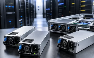
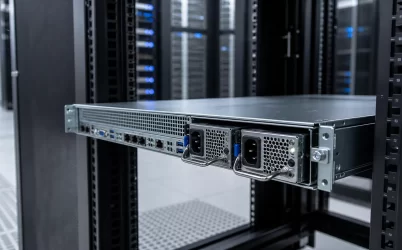
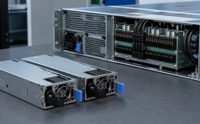
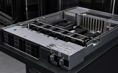
An AI server power supply must support dense accelerator loads, rapid power changes, high cooling demand, and a defined redundancy policy without exceeding the limits of the PSU modules, power-distribution board, connectors, rack PDUs, or upstream circuits. The correct design starts with the complete workload envelope and the server manufacturer’s approved power architecture. It does not start with adding GPU nameplate values or choosing the largest available module. Engineers must evaluate sustained demand, short excursions, input voltage, failure-state capacity, power capping, airflow, telemetry, and rack-level distribution together.
Quick answer: size for the worst supported operating state
Build an AI server power budget from measured or platform-qualified CPU, GPU, memory, storage, network, and fan loads. Add the required engineering margin, then repeat the calculation for every supported failure state. If the system promises continued full performance after a PSU or feed loss, the remaining modules and upstream path must carry that load under the specified input voltage, temperature, altitude, and airflow. Also verify transient response, PDB and connector current, firmware compatibility, and whether power capping is required to preserve redundancy. A large total installed wattage does not by itself prove resilient capacity.
GPU workloads change the shape of the power problem
Traditional enterprise workloads often provide useful diversity across processors, storage, and network activity. AI training and inference can synchronize many accelerators, causing a large part of the server to change state at nearly the same time. The important engineering quantity is therefore not only average power but the magnitude, duration, and repetition rate of workload-driven power changes.
A PSU and its downstream distribution must keep voltage within the platform’s acceptable range while the load changes. Board-level energy storage and voltage regulators handle part of that response, while the PSU, PDB, cables, busbars, and connectors determine the larger system behavior. A server that appears comfortable at an average 60% load can still encounter excursions that trigger current limits, voltage droop, thermal throttling, or loss of redundancy.
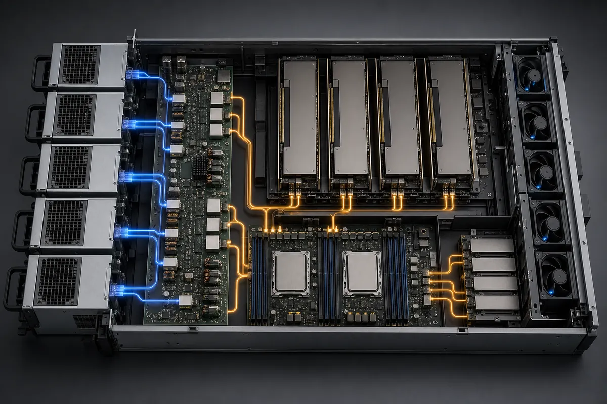
The complete load model should include accelerator boards, host CPUs, memory, local NVMe storage, network adapters, management electronics, pumps where liquid cooling is used, and fans at their qualified maximum operating point. Startup, firmware update, recovery, and degraded-cooling states may create different combinations from the normal AI workload.
Protected capacity requires more than a sum of ratings
Consider a hypothetical AI server with a measured 5.6 kW sustained accelerator load and 1.8 kW for CPUs, memory, storage, networking, and cooling. Its sustained total is:
5.6 kW + 1.8 kW = 7.4 kW.
If the design team applies 15% engineering headroom for approved configuration variation, the planning value becomes:
7.4 kW × 1.15 = 8.51 kW.
Assume the platform uses six load-sharing modules and requires four modules to carry the protected load after the allowed failures. Under an idealized equal-share calculation, each of those four modules would need to support at least:
8.51 kW ÷ 4 = 2.13 kW per active module.
This result is a screening value, not a product recommendation. Final qualification must account for the actual current-sharing tolerance, module derating, conversion losses, input voltage, thermal conditions, transient requirements, PDB limits, and the server’s control policy. If a measured short excursion reaches 9.0 kW, the system team must validate that event separately; increasing a sustained-load margin is not automatically equivalent to verifying transient performance.
The same calculation should be repeated for the rack. A server may retain enough internal PSU capacity yet shut down when too many cords share one rPDU, branch circuit, phase, or upstream source. The failure boundary must be explicit: PSU module, cord, rack PDU, breaker, transfer system, UPS path, or utility feed.
Locate power conversion at the right layer
AI infrastructure can use server-level AC PSUs, rack-level power shelves, or a combination defined by the platform. Conventional systems may convert 200–240 V AC inside each server and distribute a 12 V main output through a PDB. Higher-density designs increasingly use a rack power shelf and a 48 V or nearby nominal DC bus, or accept a higher-voltage bus into the server before conversion near the accelerators.
| Power boundary | Where conversion occurs | Primary integration questions |
|---|---|---|
| Server-level AC modules | Inside each compute system | Module bays, high-line input, PDB current, airflow, cords, redundancy logic |
| Rack power shelf and DC busbar | In shared rack-level shelves | Shelf redundancy, busbar rating, touch safety, rack management, service isolation |
| Direct DC server input | Upstream rectification with conversion inside the server | Input range, connector and bus ratings, protection coordination, grounding, telemetry |
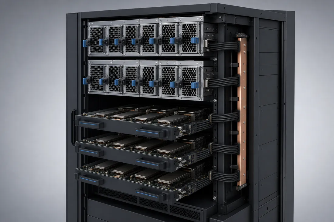
Higher-voltage distribution reduces current for the same power before downstream conversion. For an idealized 9.0 kW bus load, 12 V corresponds to 750 A, while 48 V corresponds to 187.5 A. Actual conductor and connector design must include losses, tolerances, protection, and the platform’s approved operating range. The arithmetic demonstrates the current-density trade-off; it does not establish compatibility or make one voltage universally preferable.
NVIDIA’s current DGX B300 documentation illustrates that platform choice can materially change the facility interface: the system is offered with an AC PSU approach or a 54 V DC busbar approach. Those values are specific to that product and should not be generalized to other AI servers. Open Compute Project rack specifications likewise document 48 V power-shelf concepts for compatible rack architectures.
Redundancy must survive the intended upstream failure
AI platforms may use 1+1, N+1, N+N, or manufacturer-specific redundant arrangements. The notation has meaning only when the required load, performance state, and failure scenario are defined. Some systems can continue operating with fewer active modules but reduce accelerator performance. Others require power capping to keep demand within the capacity that remains after a failure.
NVIDIA documents a 4+2 PSU arrangement for DGX H100/H200 systems and notes different behavior when additional supplies lose power. Its SuperPOD electrical guidance also connects server redundancy to multiple rack power sources. This is an important general design lesson: PSU redundancy can be defeated when supposedly independent modules depend on the same rack PDU or upstream circuit. The exact number and separation of feeds must follow the chosen platform and facility availability design.
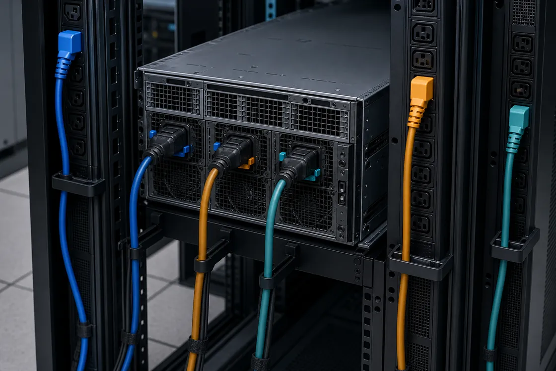
Map every PSU cord to a rack PDU and every rack PDU to its breaker, phase, transfer equipment, and UPS source. Confirm that the surviving paths can carry the post-failure load without exceeding continuous or transient limits. Phase balancing and cord retention also matter at high rack density. A correct server configuration can still fail its availability objective if the upstream mapping creates an unexpected common point of failure.
Power density becomes a thermal and connector constraint
Conversion loss becomes heat inside the module or power shelf. At AI-server power levels, even a small efficiency difference can change the cooling load, but efficiency must be evaluated over the expected operating range and input condition rather than inferred from one peak number. Redundant modules may operate at different load percentages as the control policy changes active and standby states.
Current density can also make the distribution path a limiting component. Review connector temperature rise, PDB copper, cables, busbars, fuses, contact resistance, insertion cycles, and airflow around the power bay. A module with adequate nameplate capacity cannot compensate for an undersized mating connector or a PDB that was qualified for a lower current.
Cooling validation should cover normal AI load, maximum fan or pump demand, one failed PSU fan where the platform supports operation, a removed module, blocked-flow assumptions, and the specified rack inlet conditions. High altitude reduces air density, while warm inlet air narrows thermal margin. Use manufacturer derating information rather than creating a universal correction factor.
Telemetry and power capping protect the operating envelope
Managed AI servers can expose PSU state, platform power, temperatures, faults, fan information, and redundancy policy through the BMC, PMBus-based devices, Redfish, IPMI, or platform-specific controls. Telemetry helps operators detect loss of a feed, poor load sharing, rising inlet temperature, and reduced reserve capacity. The available fields, accuracy, and update rates depend on the system.
Power capping can preserve a defined redundancy mode or prevent upstream overload by constraining the workload’s maximum power. The performance consequence depends on the application and platform policy. NVIDIA documents power-capping controls for DGX H100/H200 systems, including their relationship to PSU redundancy. That behavior is model- and firmware-specific; an integrator should validate the actual server rather than copy a threshold from another platform.
A useful operational policy combines three layers: alarms for lost modules or feeds, a power limit aligned with surviving capacity, and workload behavior that responds predictably when power is constrained. Test the policy with real training or inference jobs, because a cap that protects the electrical system may change job completion time, synchronization behavior, or checkpoint strategy.
Qualification evidence should match the deployment
- Freeze supported configurations. Record accelerator, CPU, memory, storage, network, fan, pump, and peripheral options.
- Measure the workload envelope. Capture sustained demand, representative excursions, startup, maximum cooling demand, and recovery states.
- Calculate every required failure case. Compare the load with remaining PSU, shelf, rPDU, circuit, and upstream-source capacity.
- Validate the physical power path. Review module and shelf interfaces, PDBs, busbars, connectors, cables, locking mechanisms, and service clearance.
- Run electrical and thermal tests together. Monitor voltage, current sharing, connector temperature, module temperature, airflow, and throttling during dynamic load.
- Exercise monitoring and control. Confirm telemetry, alarms, event logs, firmware, power caps, and the response to lost communication.
- Test maintenance scenarios. Remove a supported module or feed using the approved procedure and verify continued operation at the promised performance state.
For the underlying conversion and management chain, see Powernexu’s explanation of server PSU architecture and control. A model-specific example such as the HKS3600D2 54 V CRPS product page can be used to begin a component review, but its published specifications must be matched to the target chassis, PDB, bus architecture, cooling system, and qualification plan.
Does every GPU server need a 48 V or 54 V power bus?
No. Higher-voltage distribution is useful in some high-current designs, while qualified 12 V or server-level AC architectures remain appropriate for others. Use the platform’s supported topology.
Can total PSU wattage be used as the AI server power budget?
Not by itself. The budget must reflect surviving capacity in the required redundancy state, dynamic-load behavior, derating, PDB and connector limits, and upstream distribution.
Why does an AI server throttle after losing a power feed?
The remaining power path may support continued operation but not full uncapped demand. Some platforms deliberately reduce performance to stay within the available electrical or thermal envelope.
What data should be monitored during deployment?
Useful signals may include input and output power, module presence, current sharing, temperatures, fan state, warnings, faults, redundancy status, rack-feed state, and active power limits, subject to platform support and sensor validation.
An AI power design is complete only when the accelerator workload, server hardware, cooling system, module redundancy, rack distribution, and facility sources have been tested as one operating system. That evidence—not installed wattage alone—shows whether the platform can sustain the intended performance through normal load changes and the failures it is designed to tolerate.