A 1U server power supply is a compact PSU designed to operate within—or as a removable module for—a server chassis that occupies one rack unit. The “1U” label describes the server’s rack height, not a universal PSU shape. Before selecting a supply, verify the chassis power bay, mating connector or power-distribution board (PDB), airflow direction, input voltage, output rails, management protocol, and redundancy behavior. A unit that fits physically may still be electrically or logically incompatible.
Quick answer: what should you check first?
Start with the server or chassis compatibility list rather than wattage alone. Confirm the PSU envelope and insertion depth, output voltage, blind-mate connector, PDB current rating, fan direction, AC input range, hot-swap support, and PMBus or other management requirements. For 1+1 redundancy, each installed module normally must be able to carry the required protected load by itself; adding two equal-rated modules does not automatically double the redundant capacity. Finally, calculate sustained and transient demand under the intended CPU, GPU, memory, drive, and fan configuration, including applicable derating and thermal limits.
What “1U server power supply” actually means
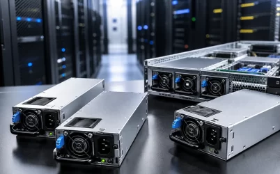
One rack unit is a chassis-height convention, while the power supply is a component integrated into that chassis. A 1U server may use a single fixed supply, two narrow hot-swappable modules, or another platform-specific arrangement. Many enterprise designs use compact common redundant power supply (CRPS) modules, but “1U” and “CRPS” are not interchangeable terms.
This distinction matters because there is no safe assumption that two supplies marketed for 1U equipment share the same mechanical envelope, connector, pin assignment, firmware behavior, or power-distribution interface. The chassis documentation and approved-parts list remain the primary compatibility references. If you are developing a new platform rather than replacing a field unit, evaluate the PSU, PDB, chassis mechanics, cooling system, and baseboard management controller as one power subsystem.
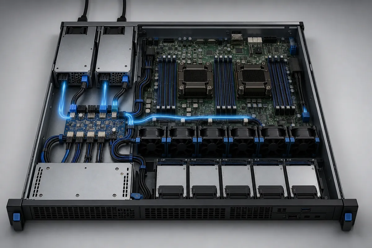
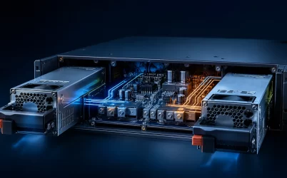
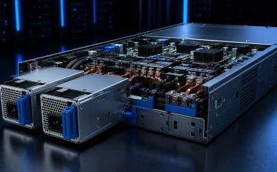
The cutaway view illustrates the system-level relationship: AC power enters the modules, conditioned DC power reaches the PDB or backplane, and the platform distributes it to processors, memory, storage, cooling, and auxiliary circuits. The exact topology and connectors vary by server design.
Fixed, hot-swap, and redundant architectures
| Architecture | Typical advantage | Important limitation |
|---|---|---|
| Single fixed PSU | Lower component count and straightforward packaging | Service usually requires shutdown; the PSU is a single point of failure |
| Single hot-swap module | Fast physical replacement where the platform supports it | Removing the only active module interrupts power |
| 1+1 redundant modules | One module can support the protected load while the other provides redundancy | Each module and the shared power path must be qualified for the required load |
| 2+0 combined power | Two modules may supply a load above one module’s capacity in supported systems | The system is not power-redundant at that load |
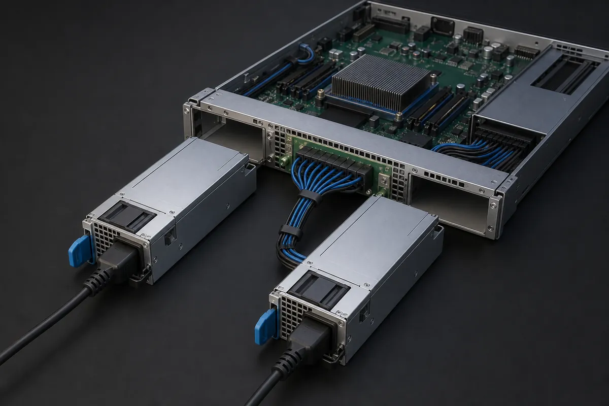
Hot swap describes serviceability, while redundancy describes continued operation after a defined failure. They are related but different. A hot-swappable PSU does not provide redundancy when it is the only installed supply. Likewise, installing two supplies does not guarantee 1+1 operation if the platform uses both to support a load greater than one module can carry.
Intel documents this conditional behavior in server platforms that support 1+0, 1+1, and 2+0 modes: when system demand exceeds one module’s capacity, the second module contributes power and redundancy is lost. The specific control logic is platform-dependent, so check the server technical specification rather than assuming a universal operating mode. Powernexu’s overview of server power supply selection provides additional system-level criteria.
Size the protected load, not just the nameplate total
PSU sizing should begin with measured or platform-qualified peak demand. Processor and accelerator power limits, memory population, storage spin-up, high fan speed, add-in cards, USB loads, and conversion losses can all affect the result. Average utilization from an existing workload is useful operational data, but it may not represent startup, boost, fault-recovery, or synthetic stress conditions.
Consider a hypothetical 1U server with a measured 720 W maximum sustained DC load during its approved stress test. The integrator applies 15% engineering headroom for configuration variation:
720 W × 1.15 = 828 W required protected capacity.
For a true 1+1 design, one active module must support at least that 828 W requirement under the specified input voltage, temperature, altitude, and airflow conditions. Two 800 W modules would not meet the example requirement as a redundant pair, because one 800 W module cannot carry the protected load. Two suitably qualified 1,000 W-class modules could provide enough nameplate headroom in this simplified example, but final approval still depends on the manufacturer’s derating curves, transient limits, PDB capacity, connector temperature rise, and server qualification data.
This calculation is intentionally system-generic. It does not imply that every 720 W server requires the same margin, or that a particular nominal rating is compatible with a given chassis.
Electrical and mechanical compatibility checklist
Output architecture and current path
Identify whether the platform expects a main 12 V output, a higher-voltage distribution architecture, auxiliary standby power, or multiple direct rails. The nominal wattage does not answer this question. Verify the PSU output specification against the PDB and motherboard design, including current limits at connectors, busbars, copper planes, cables, and protection devices.
Connector, keying, and insertion mechanics
A blind-mate connector must align correctly throughout the service life of the chassis. Check module width, height, depth, handle and latch clearance, guide rails, connector keying, insertion force, and the ability to remove the PSU without disturbing network or peripheral cables. Do not adapt an unverified pinout merely because the housing appears to fit.
Input voltage and available output
Some high-power server supplies deliver their highest rated output only within a specified high-line AC range. At lower line voltage, available power may be reduced or the operating range may differ. Confirm the exact input condition at the rack, including power-distribution unit ratings, branch-circuit limits, plugs, cords, and regional requirements.
Management and platform control
Server PSUs may exchange status, telemetry, inventory, warning, and fault information with the BMC through PMBus or a platform-specific implementation. Confirm protocol revision, device addressing, supported commands, firmware expectations, and fault-handling behavior. Electrical output alone does not prove management compatibility.
Thermal design is a selection constraint
A 1U chassis has limited vertical space and usually relies on a carefully controlled front-to-rear pressure path. PSU losses become heat inside a small volume, and dense components create resistance to airflow. Higher conversion efficiency can reduce heat for a given delivered load, but the actual result depends on the certified model, operating point, input voltage, fan policy, and ambient conditions.
Do not block the PSU inlet or exhaust with cable bundles, rack doors, or adjacent equipment. Confirm that the module’s airflow direction matches the chassis. A reverse-flow unit can recirculate warm air or compete with the system fans even when its electrical specifications appear suitable. Also review temperature and altitude derating: reduced air density can lower cooling capability, while high inlet temperature may reduce available output or accelerate component aging.
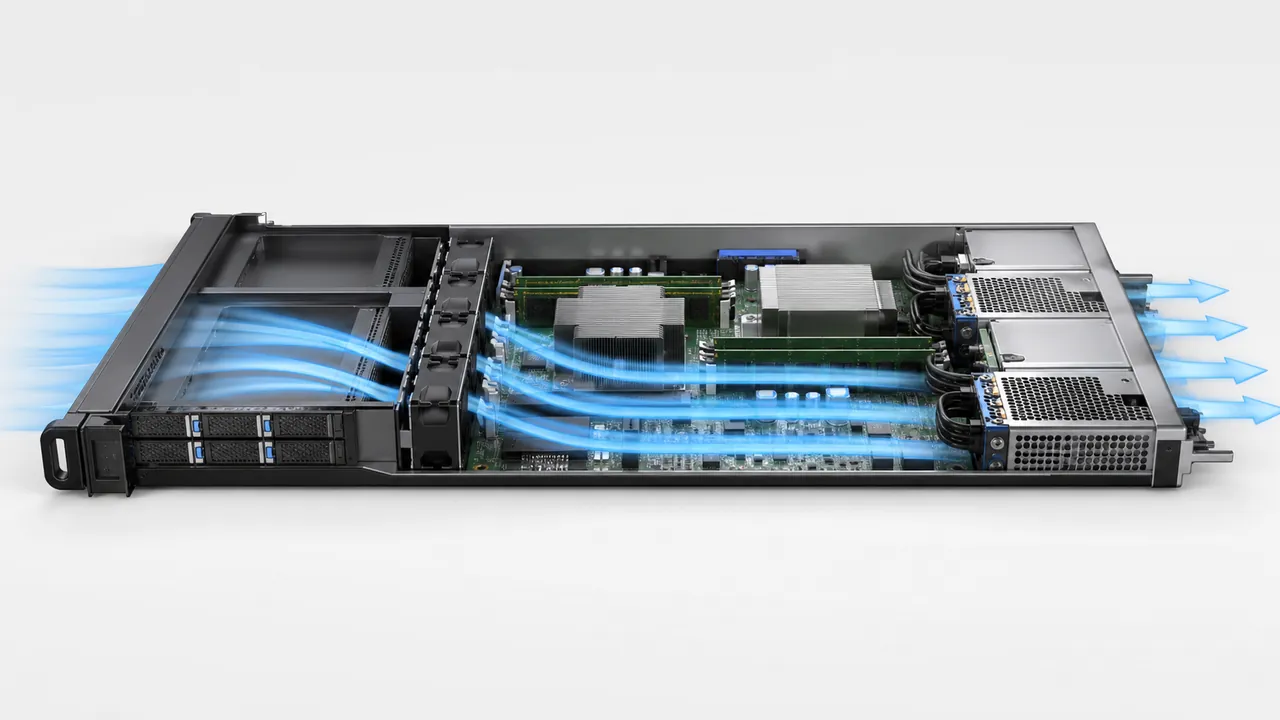
During qualification, measure temperatures and fan behavior at representative rack inlet conditions and worst-case component loading. Validate not only normal steady state but also fan failure response, a PSU removal event, dust loading assumptions, and the thermal transition when one module takes the full protected load.
Efficiency, power quality, and protection
Efficiency affects facility energy use and internal heat, but a badge or peak figure should not be treated as the entire selection decision. Compare efficiency over the load range the server will actually use. In a redundant system, the active modules may operate at a different percentage of rated capacity than a single module, and some platforms use cold-redundancy control to change which module is active at lighter loads.
Review input power factor, inrush behavior, leakage current, conducted and radiated emissions, output ripple, transient response, hold-up behavior, and protection coordination where the server specification makes them relevant. Protection functions such as overvoltage, overcurrent, short-circuit, and overtemperature protection should be evaluated at system level: the BMC, PDB, motherboard, and workload-control policies determine how the server responds to warnings and faults.
How to qualify a 1U server PSU
- Freeze the platform configuration. Record CPU, accelerator, memory, storage, NIC, fan, and peripheral populations, including permitted future options.
- Confirm the approved mechanical interface. Compare the chassis bay, guides, latch, connector, service clearance, and airflow direction with controlled drawings.
- Map the complete electrical path. Validate input conditions, output rails, standby power, PDB ratings, connector current, and protection coordination.
- Measure representative demand. Test startup, sustained stress, transient workloads, maximum fan operation, and recovery scenarios rather than relying only on software-estimated average power.
- Test the intended redundancy mode. Verify operation after removing input power from either module and after physically removing a module, within the platform’s approved procedure.
- Validate management behavior. Confirm inventory, telemetry, warnings, event logs, firmware compatibility, and fault reporting through the BMC.
- Complete thermal and compliance review. Use the actual chassis, rack environment, cables, input distribution, and required regional approvals.
For a verified product example, the Powernexu CRPS1300N2 product page documents a compact CRPS option for server platforms. Treat its published specifications as model-specific; suitability still depends on the target chassis, PDB, input conditions, airflow, and platform qualification.
Questions engineers and buyers often ask
Is every 1U power supply interchangeable?
No. “1U” identifies the server chassis height, not a universal PSU interface. Mechanical dimensions, connectors, pin assignments, airflow, management, output rails, and firmware support can differ.
Do two 1,000 W PSUs provide 2,000 W with redundancy?
Not in a 1+1 configuration. Protected capacity is generally limited to what one module can support under the specified conditions. A platform may use both modules in a combined, nonredundant mode, but that behavior must be explicitly supported and qualified.
Can a higher-wattage module replace a lower-wattage unit?
Only if the server or chassis vendor supports that exact module and configuration. Extra nameplate capacity does not establish connector, cooling, management, or firmware compatibility, and mixed modules may not support redundancy.
What information should be included in an RFQ?
Provide the chassis or platform, required output architecture, protected load, redundancy mode, AC or DC input range, mechanical envelope, mating connector or PDB, airflow direction, ambient and altitude range, management protocol, compliance markets, and expected qualification tests.
Make the power subsystem a platform decision
The most reliable selection process treats the PSU as part of the complete 1U server rather than as a stand-alone wattage source. Begin with compatibility, calculate the protected load, and then validate redundancy, input conditions, power distribution, management, and cooling on the real platform. That sequence prevents the common failure mode of choosing a compact module that looks adequate on paper but cannot safely deliver the required capacity—or communicate and cool correctly—in the target server.