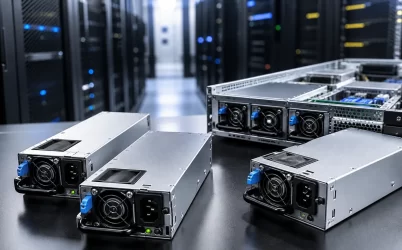
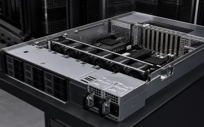
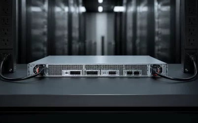
A CRPS redundant power supply is a modular server power subsystem built around replaceable power modules, a compatible power-distribution board (PDB), and platform management. CRPS can simplify mechanical integration and service across qualified designs, but the label does not make modules universally interchangeable. Reliable redundancy depends on the complete interface: output architecture, connector and PDB ratings, current sharing, hot-plug behavior, airflow, PMBus implementation, firmware, input power paths, and the load that must remain supported after a failure.
Quick answer: qualify the subsystem, not the module alone
Begin with controlled specifications for the CRPS module, chassis bay, blind-mate connector, PDB, BMC, and approved firmware. Confirm that one module—or the required surviving set—can support the protected load under the actual input voltage, temperature, altitude, and airflow. Then test insertion and removal, load transfer, current sharing, fault isolation, telemetry, alarms, and recovery. Matching wattage and a similar enclosure are insufficient evidence. A redundant design is proven only when the integrated server continues operating through its defined failure and maintenance scenarios.
CRPS standardization has a defined boundary
Common Redundant Power Supply specifications provide a framework for modular server power, including mechanical, electrical, and management-related interfaces. Current industry work also includes modular CRPS specifications within Open Compute Project server architecture. Standardization can reduce custom engineering, but implementations still vary by specification revision, power class, output voltage, connector option, airflow, management profile, and platform policy.
That boundary matters during sourcing. A module may fit the bay yet use a different connector implementation, standby behavior, addressing scheme, firmware expectation, or output architecture. Treat the server or chassis approved-parts list as the starting point for replacement. For a new design, compare controlled drawings and interface specifications rather than relying on a product-category name.
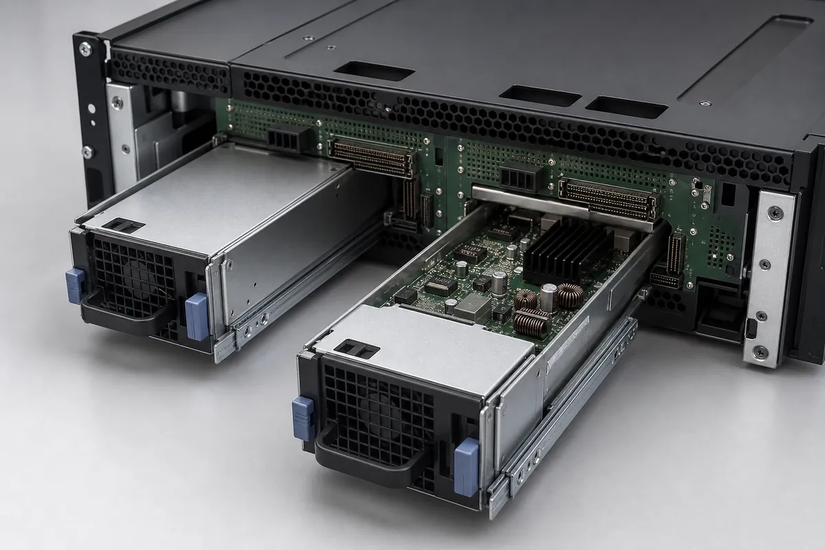
The PDB completes the redundant power path
The modules convert input power, while the PDB or backplane accepts their outputs, combines or isolates the channels as designed, and distributes power to the motherboard and other loads. The PDB may also route standby power, presence signals, address pins, status lines, and the management bus. It is therefore an active integration constraint even when it performs no main voltage conversion.
| Interface area | Integration question | Failure if overlooked |
|---|---|---|
| Mechanical alignment | Do guides, latch, depth, connector offset, and service clearance match? | Incomplete seating, damaged contacts, or blocked removal |
| High-current path | Can contacts, copper, cables, and protection carry normal and failure-state current? | Voltage drop, overheating, or nuisance protection trips |
| Standby and control | Are presence, enable, sequencing, and standby behavior compatible? | Failure to start, stop, or transfer load correctly |
| Management channel | Do addressing, commands, scaling, and firmware expectations agree? | Missing telemetry, false alarms, or unsupported control |
Connector temperature rise deserves particular attention. At high current, small increases in contact resistance can create localized heat. Qualification should use the real module, PDB, chassis pressure, airflow, and expected insertion-cycle condition—not an electrically convenient bench connection that bypasses the production interface.
Capacity must be checked after a module is lost
Two installed modules do not automatically provide twice the redundant capacity. In 1+1 operation, each module normally must support the protected load by itself. Some platforms can use both modules in a combined 2+0 mode, but redundancy is then lost when the load exceeds one module’s capability. Intel documents this distinction for systems that change operating mode according to load.
Consider a hypothetical server with a measured 1,080 W sustained DC load. Applying 15% engineering headroom gives:
1,080 W × 1.15 = 1,242 W protected capacity.
A pair of 1,200 W modules would not satisfy this simplified 1+1 requirement because one surviving module is below 1,242 W. A higher-rated compatible module may pass the initial capacity screen, but final approval still depends on input-voltage derating, temperature, altitude, transient response, PDB limits, and the manufacturer’s supported configuration. The same failure-state calculation should include maximum fan demand and any workload or firmware power cap used after a fault.
Hot plug requires coordinated sequencing
Hot-swappable hardware is designed for supported replacement while the server remains energized, but safe operation depends on connector sequencing, inrush control, output isolation, load transfer, firmware, and the documented service procedure. The remaining power path must already have sufficient capacity before a module is removed.
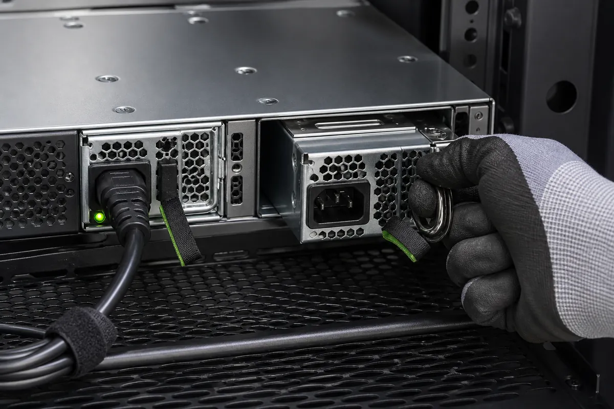
During testing, remove input from the target module before extraction when required by the platform procedure, confirm that its output is isolated, and monitor the surviving module, PDB voltage, connector temperature, event log, and workload. Reinsert the module and verify controlled startup, current-sharing recovery, correct inventory, and clearance of the fault state. Never infer hot-swap support solely from the presence of a handle.
Current sharing and transients interact
When multiple modules operate in parallel, current-sharing control keeps one unit from carrying a disproportionate load. Sharing tolerance affects temperature, fan speed, efficiency, and the margin available during a workload step. A system can have adequate combined nameplate power yet overstress one module if sharing, wiring resistance, connector resistance, or control-loop interaction is poor.
Test steady loads across the expected operating range, then apply representative server transients. Measure each module’s current, bus voltage, recovery time, PDB drop, and thermal response. Repeat with the load paths and input feeds arranged as they will be deployed. Average telemetry alone may miss a short excursion or oscillation, so use suitable measurement equipment for qualification.
PMBus data must match BMC expectations
PMBus is an open-standard protocol for managing power converters, and an application profile exists for AC/DC server power supplies. A supported CRPS implementation may expose identification, voltage, current, power, temperature, fan, warning, and fault information. Exact commands, formats, accuracy, addressing, and control permissions remain module- and platform-specific.
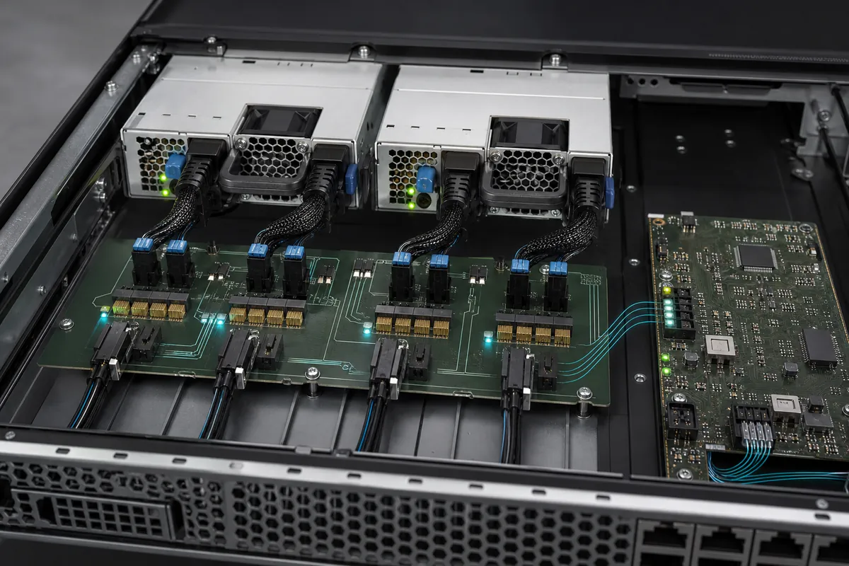
For redundant bays, verify that address selection is unique and stable, the BMC identifies each physical slot correctly, sensor scaling is interpreted correctly, and replacing a module does not create stale inventory or false faults. Test communication loss as well as electrical faults. Management compatibility cannot be proven by electrical bus continuity or an “I2C compatible” statement alone.
Use an integration-focused qualification plan
- Control the configuration. Record module revisions, PDB revision, connector option, chassis, BMC firmware, BIOS, and supported server loads.
- Inspect fit and airflow. Verify guides, latch, seating, service clearance, inlet and exhaust direction, and obstruction risk.
- Audit the current path. Check PDB copper, contacts, cables, protection, standby rails, grounding, and temperature rise.
- Prove protected capacity. Run the maximum supported load with each allowed module or input-path failure.
- Exercise dynamic behavior. Test load steps, current sharing, transfer, insertion, removal, startup, and recovery.
- Validate management. Confirm addresses, inventory, telemetry, warnings, faults, event logs, and replacement behavior.
- Repeat under environmental limits. Apply the specified input, temperature, altitude, airflow, and maintenance conditions.
Powernexu’s article on CRPS power-distribution board design provides more detail on the high-current interface, while the CRPS1300N2 product page offers a verified model-specific reference. Published model data should still be matched to the target platform rather than generalized across all CRPS products.
Can CRPS modules from different manufacturers be mixed?
Only when the server or platform documentation explicitly supports the exact combination. Similar mechanics and ratings do not prove sharing, management, firmware, or fault compatibility.
Does CRPS guarantee hot swap?
The module form supports service-oriented designs, but the complete server must implement and qualify the required hot-plug behavior. Follow the platform-specific procedure.
Why does the BMC report errors after a replacement?
Possible causes include unsupported firmware, address or inventory mismatch, incompatible commands, stale events, incomplete seating, or a module combination the platform does not approve.
What should an RFQ include?
Include the target CRPS specification and revision, power and input conditions, output architecture, mechanical drawing, connector/PDB interface, airflow, redundancy mode, management requirements, environmental limits, compliance markets, and required qualification evidence.
A successful CRPS deployment is therefore an interoperability result. The module, PDB, chassis, cooling, BMC, firmware, input feeds, and workload must behave as one qualified redundant subsystem during normal operation, service, and every failure state the server is expected to survive.