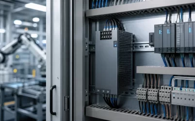
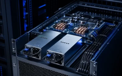
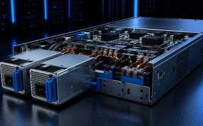
An open frame power supply is an AC-DC converter built on an exposed printed circuit board for installation inside a larger piece of equipment. Removing the external metal case saves space and gives the system designer more freedom over mounting and airflow, but it also transfers important responsibilities to the host equipment. Mechanical protection, electrical access, insulation, cooling, grounding, and final-system compliance all depend on how the supply is integrated.
That trade-off makes selection different from choosing an external adapter or a fully enclosed industrial supply. The nameplate output is only the starting point. A reliable design must match the real load profile, input conditions, enclosure temperature, mounting orientation, airflow path, safety architecture, and electromagnetic environment.
What an Open Frame Supply Changes at System Level
The exposed-board construction is intended for original equipment manufacturers and system integrators. It can be a strong fit for test instruments, communications equipment, displays, medical equipment, industrial controls, embedded computers, and other products that already provide a protective enclosure. The supply becomes a component within that final product rather than a standalone appliance.
This arrangement can reduce volume and avoid a second enclosure inside the equipment. It can also place the conversion stage close to the load and allow the system fan to cool several assemblies. The corresponding design burden is significant: users must be protected from hazardous energy, the PCB must be supported without mechanical stress, conductive objects must not contact the board, and heat must leave the enclosure under the worst credible operating condition.
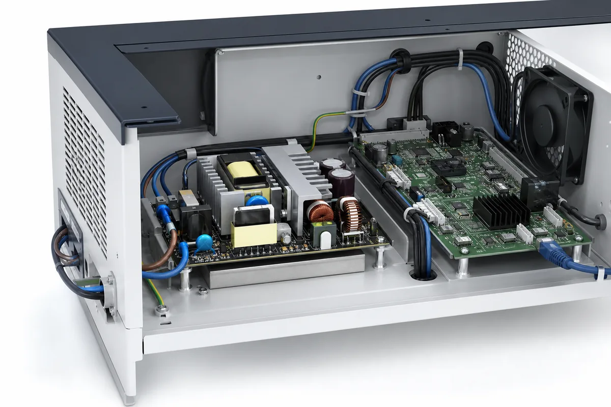
Do not assume that an open board can be mounted wherever space remains. The recommended orientation, keep-out areas, standoff locations, insulation distances, and cooling conditions in the manufacturer documentation are part of the design input. Cable routing and nearby assemblies can change both electrical clearance and airflow after the initial mechanical layout appears complete.
Start With the Electrical Load, Not the Wattage Label
List every required output rail, its normal current, startup demand, short-duration peaks, sequencing needs, and tolerance at the actual load connector. Motors, capacitive loads, processors, displays, pumps, and radio transmitters can create load steps that are much higher than their steady-state demand. A supply that appears adequate by average power may enter current limit during startup or allow an important rail to dip during a transient.
Review the complete operating envelope rather than a single nominal point:
- minimum and maximum AC input expected at the equipment terminals;
- continuous, peak, and startup output requirements;
- acceptable output tolerance, ripple, and transient deviation;
- hold-up behavior during brief input interruptions;
- minimum-load or preload requirements for every output;
- remote sense, power-good, inhibit, or auxiliary-output needs;
- the recovery behavior of overcurrent, overvoltage, short-circuit, and overtemperature protection.
Use the datasheet test conditions when comparing candidates. Output power available with natural convection may differ from the rating available with specified forced airflow. Peak ratings may also be limited by duration, duty cycle, input voltage, or temperature. Treat each condition as part of the rating rather than as a footnote.
Choose the Construction That Fits the Equipment
| Construction | Best Fit | Primary Integration Concern |
|---|---|---|
| Open frame | Compact OEM equipment with its own protective enclosure | Safety barriers, mounting, airflow, and final-system compliance |
| Enclosed chassis | Equipment that benefits from added mechanical protection | Ventilation, mounting space, and chassis grounding |
| DIN-rail supply | Control panels and field-serviceable industrial cabinets | Rail space, cabinet temperature, and wiring access |
Open frame construction is not automatically the smallest finished solution. Required barriers, insulating sheets, connectors, finger-safe covers, wiring space, and air clearances can consume part of the apparent volume advantage. Compare candidates using the complete installed assembly, not only the PCB outline.
Mechanical details deserve the same attention as electrical ratings. Confirm board dimensions, mounting-hole coordinates, permitted screw and spacer arrangements, connector locations, maximum component height, and access for production assembly. Standoffs should support the board without bending it, and the design should prevent loose hardware or cable movement from reaching live circuitry.
Thermal Performance Belongs to the Final Enclosure
Open frame supplies expose their heat-generating components directly to the air, but that does not guarantee effective cooling. Natural convection depends on orientation, free space around the board, vent placement, and a continuous path for cooler air to enter while warm air exits. A nearby cable bundle, display panel, or horizontal shelf can create a recirculation pocket even when the enclosure has ventilation openings.
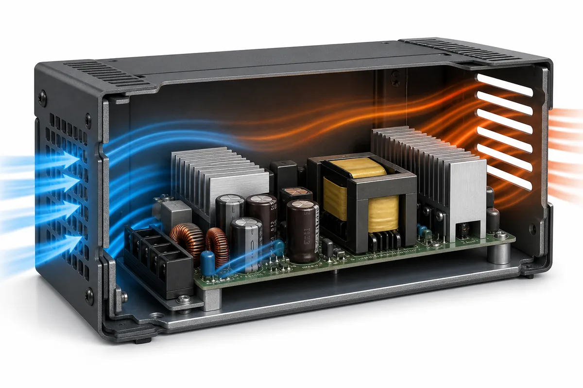
If forced air is required, reproduce the airflow direction and minimum conditions stated for the rating. A fan specification by itself is not enough; filters, grilles, pressure drop, component blockage, fan aging, and system altitude can reduce the flow that actually crosses critical components. The inlet temperature at the power supply can also be higher than room temperature because other assemblies preheat the air.
Validate the completed enclosure at low line, maximum intended load, maximum ambient temperature, and the least favorable approved orientation. Measure the manufacturer-identified critical components where guidance is available. Apply the published temperature and input-voltage derating curves rather than creating an informal safety margin around the headline wattage.
Safety Approval Is a System Integration Input
A component safety approval is valuable, but it does not make every installation compliant. The final equipment determines whether users can access hazardous parts, whether protective earth remains reliable, whether required insulation distances are maintained, and whether the supply is used within its conditions of acceptability.
Select a supply evaluated for the end product’s applicable safety context, then obtain the safety report or installation conditions needed by the certification team. Check the required spacing above, below, and around the board; the insulation provided by the equipment chassis; the treatment of accessible connectors; and the separation of input wiring from low-voltage circuits. Exact distances and classifications are product- and application-specific, so they must come from the selected supply’s documentation and the governing end-equipment standard.
Grounding also affects safety and noise performance. Keep protective-earth connections short, secure, and appropriate for the required fault current. Do not casually join output return, signal ground, chassis, and protective earth at multiple points. Define the grounding architecture before the mechanical layout is frozen.
EMI Performance Must Be Confirmed in the Finished Product
An open frame converter may be tested to specified emissions and immunity conditions, yet the host wiring and enclosure can materially change the result. Long input or output leads add loop area, cable bundles couple noise between circuits, and an unplanned chassis connection can create a common-mode path. Conversely, a well-designed metal enclosure and disciplined cable routing can improve containment.
Place input wiring away from sensitive low-level signals, minimize high-current loop area, and follow the manufacturer’s grounding and external-filter guidance. If additional filtering is needed, verify that it does not create unwanted leakage current, resonance, startup behavior, or stability problems. Conducted and radiated emissions should be tested with representative cable lengths, loads, peripherals, and enclosure panels installed.
Match Environmental Protection to the Deployment
Because the PCB is exposed, the host enclosure must manage dust, conductive debris, moisture, cleaning fluids, and accidental contact. In a controlled indoor instrument, this may be straightforward. In a factory cabinet, kiosk, transportation system, or humid location, contamination risk can dominate the architecture.
Evaluate operating temperature, humidity, altitude, vibration, and shock using verified product data. If conformal coating or another protective option is required, confirm exactly what is coated and what environmental benefit the manufacturer supports. Coating does not replace enclosure sealing, correct creepage and clearance, or thermal validation.
A Practical Selection and Validation Sequence
- Define the AC input range and every DC load condition, including startup and transient demand.
- Choose the required safety context, grounding class, interfaces, and protection behavior.
- Compare power ratings under the intended convection or forced-air condition.
- Build the mechanical layout with documented standoffs, keep-out regions, insulation, wiring access, and airflow.
- Prototype with representative cables, loads, enclosure panels, filters, and fans.
- Validate electrical performance, critical temperatures, abnormal operation, EMC, and safety in the final configuration.
Powernexu’s open frame power supply range provides a useful starting point for comparing available board-level formats. Final selection should still be based on verified specifications and the complete equipment-level validation plan.
The right open frame supply is not simply the smallest board with enough nominal watts. It is the converter whose electrical limits, safety conditions, cooling method, mechanical arrangement, and EMC behavior can all be reproduced inside the finished product. Treating those conditions as part of the power-supply specification leads to a more predictable certification process and a more reliable system.