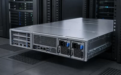
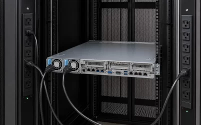
A 3000W Titanium redundant server PSU should be treated as a high-power platform component, not as a universal replacement identified by four catalog terms. The initial shortlist may include a 1U removable module, an M-CRPS hot-plug kit, or a CRPS/M-CRPS product intended for integration into a matched cage and power distribution board (PDB). Before purchasing, establish the exact product identity, supplied hardware, supported host, mating interface, airflow direction, input conditions, and output available with one module unavailable. The 3000W rating identifies a capacity class; it does not prove interchangeability or guarantee 3000W of protected server load in every configuration.
Manufacturer listings show why the query is not a complete specification. The HPE 3000W M-CRPS Titanium hot-plug reverse-airflow AC power supply kit documents one exact combination of wattage, architecture, efficiency class, service method, airflow, and package type. Those fields apply to that product identity; they do not establish interchangeability with another 3000W listing or prove contents not stated in its documentation.
For every candidate, record the manufacturer, exact part number, revision, and supplied product noun. A bare module assumes that a compatible bay, PDB, controls, and downstream distribution already exist. A kit requires an itemized bill of materials. CRPS or M-CRPS narrows the architecture family but does not authorize installation in every chassis carrying that label.
| Listing field | What it establishes | What still requires evidence |
|---|---|---|
| 3000W | A nominal output class under documented conditions | Output at the deployed input and with one module unavailable |
| Titanium | An efficiency classification for the identified product | Host compatibility, availability, and actual facility demand |
| Module or kit | The stated commercial package type | Exact included hardware and installation dependencies |
| CRPS or M-CRPS | An architecture family | Mechanical variant, PDB, signals, firmware, and host approval |
Shortlist only exact identities that can be tied to the intended host. Treat missing dimensions, interfaces, operating limits, or package contents as verification requirements rather than inferred facts.
CRPS and M-CRPS names do not close the platform boundary
CRPS and M-CRPS reduce some integration ambiguity by defining modular server-power ecosystems, but a family designation is not the same as a complete interchangeable-part declaration. A deployable configuration joins the removable PSU to the chassis bay, retention hardware, blind-mate interface, PDB, management implementation, cooling path, and host support record.
The mechanical comparison should begin with controlled drawings for the exact revisions. Body height, width, and depth are only the outer envelope. The insertion rails, front flange, latch position, handle travel, connector seating plane, keying, insertion stop, ventilation openings, and extraction path can disqualify a candidate that appears to occupy a similar rectangular volume. High-power modules also need enough rear service clearance for removal without disturbing rack cabling or adjacent equipment.
The blind-mate connection then transfers power and control into the PDB. Physical engagement does not establish an electrical match. Main-power contacts, standby functions, enable and status signals, current-sharing behavior, presence detection, and management communications must correspond to the host implementation. Exact pin assignments and management behavior are model-specific and should come from controlled documentation rather than visual comparison.
Powernexu’s overview of server PSU form-factor ecosystems explains how the module, cage, connector, PDB, airflow path, and service model form one compatibility chain. For a 3000W procurement, the practical implication is narrower: record which CRPS or M-CRPS implementation the candidate belongs to and require evidence tying that implementation to the intended host.
A deployable 3000W assembly must close five boundaries
A useful qualification matrix separates five boundaries that marketplace descriptions often compress into a single product title. Each boundary has a different evidence owner, and an unanswered field should remain visible instead of being filled by an assumption.
| Boundary | Required evidence | Typical disqualifying gap |
|---|---|---|
| Product identity | Manufacturer, exact part number, revision, product type, and controlled datasheet or host record | An offer permits an unspecified “equivalent” or uses a stock image without label evidence |
| Assembly scope | Module quantity and an itemized list of cage, PDB, harnesses, cords, mounting parts, and accessories | The price covers one module while the project assumes a complete redundant assembly |
| Host interface | Supported server or chassis, bay and mating-interface drawings, PDB identity, control behavior, and relevant firmware conditions | Compatibility is claimed from wattage, external dimensions, or CRPS wording alone |
| Operating envelope | Applicable input, output, inlet temperature, altitude, airflow, derating, and protection documentation | The 3000W figure is quoted without the conditions under which it is available |
| Redundant state | Supported topology, permitted server load after a module or feed loss, current transfer behavior, and management response | Two module ratings are added together and presented as protected capacity |
The matrix should be completed for each exact candidate rather than for a generic “3000W Titanium PSU.” This prevents evidence from one model being used to close a gap in another. It also keeps a platform vendor’s host approval distinct from a component supplier’s product specification: both may be valuable, but they support different claims.
The protected power number appears after one module is lost
In a typical 1+1 arrangement, both installed modules can share the normal load, while either module is expected to carry the supported server state after its partner becomes unavailable. Two 3000W labels therefore do not automatically produce 6000W of fault-tolerant output. Protected capacity is constrained by the documented capability of the surviving path under the deployed input and environmental conditions, together with any limits imposed by the host, PDB, connectors, cooling system, or operating policy.
For example, consider a hypothetical server whose required degraded state includes a defined CPU and accelerator configuration, memory, storage, fans, and management functions. The procurement team should compare that state with the output the exact module and platform support when one PSU is absent. If the server is permitted to reduce workload or apply power caps after a fault, the reduced state must be explicit. A response that depends on undocumented throttling is not equivalent to continuous support of the original workload.
Current sharing also changes after a module loss. During normal operation, two healthy modules may divide load. When one disconnects, the surviving module and its PDB path take the full required current, and its conversion losses and thermal load rise accordingly. The transition matters as well as the final steady state: the common bus must remain within the host’s accepted behavior while source current transfers. Exact transient limits and sharing tolerances are product-specific, so the RFQ should request the applicable platform evidence rather than impose invented universal values.
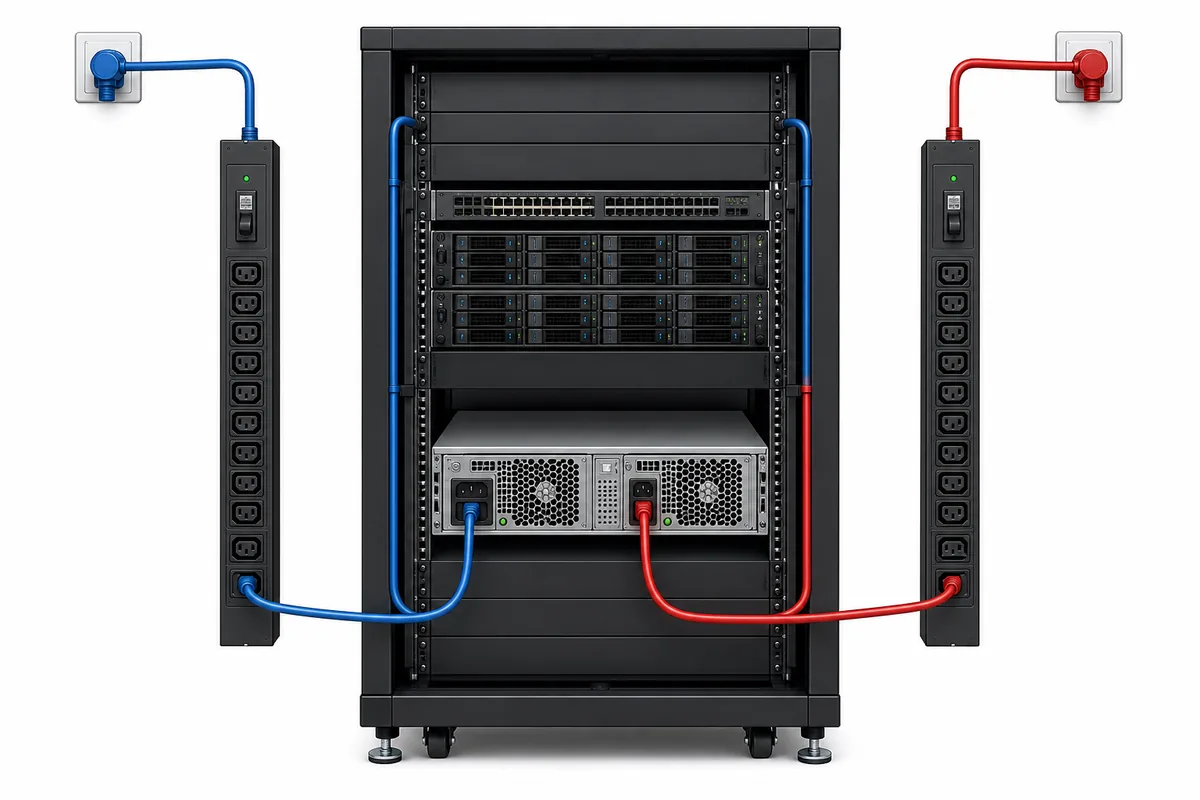
Redundancy should also name the failure being covered. Two modules connected through one PDB can protect against a defined module failure while retaining shared dependencies in the cage, common bus, management path, cooling system, or upstream source. Connecting the modules to separate rack feeds can extend protection upstream, but only if the server implementation and facility distribution preserve that separation. “Redundant” is meaningful when the quotation states the covered event and the operating state that survives it.
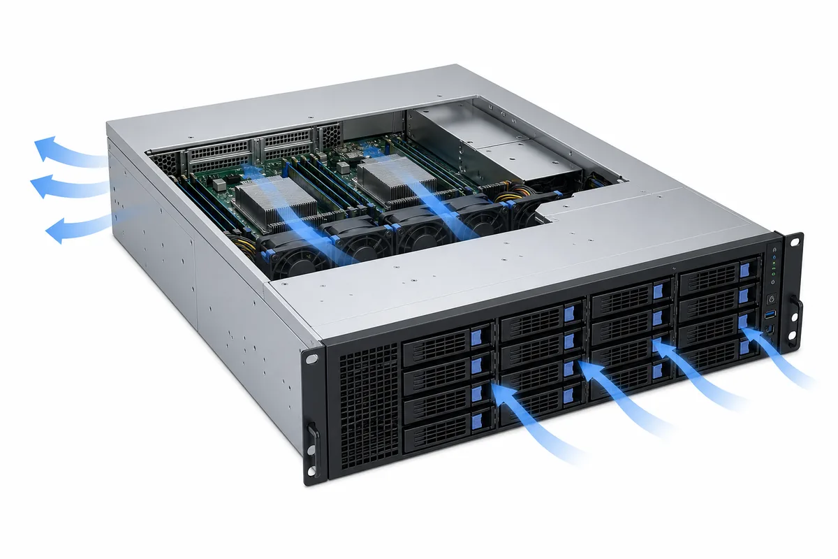
At 3000W, airflow direction becomes a hard deployment gate
A high-output module concentrates conversion loss in a small server-power enclosure. Titanium efficiency can reduce loss relative to a less efficient design at comparable operating conditions, but it does not eliminate heat, and the badge does not specify how the host must move air through the exact PSU. The module’s documented airflow direction, pressure requirement, inlet-temperature boundary, fan behavior, and any output derating must agree with the chassis cooling design.
Airflow direction is especially important because manufacturer listings can describe normal or reverse-airflow variants. A reverse-airflow kit is not merely a different fan preference. Installing a module whose flow opposes the chassis can create recirculation, reduce local cooling, or disturb pressure relationships around neighboring components. Matching the electrical interface does not correct an incompatible thermal path.
The failed state is the more demanding thermal case for the PSU subsystem. When one module is removed or inactive, the remaining converter may carry substantially more load, while the empty bay can alter airflow unless the chassis design controls that opening. The platform documentation should define whether a blank, closed latch, service-time limit, fan response, or another condition applies. Those details should not be inferred from a different server using a visually similar module.
Service access belongs to the same boundary. The technician needs enough extraction space to release and remove one module without pulling the healthy module, blocking its inlet or exhaust, or placing force on nearby cords. A 3000W hot-plug product creates an online replacement opportunity only when the server remains within its one-module operating envelope throughout the procedure.
The rack must support the high-power operating states
The PSU’s input documentation controls whether the module can deliver its rated output at the intended rack location. The voltage and frequency range, input-current behavior, cord and inlet requirements, and any power limitation at input conditions must be obtained for the selected model. A generic assumption about high-line operation is not a substitute for its datasheet and host documentation.
At this power class, the input decision propagates through the branch circuit, rack PDU, outlet, cord set, UPS allocation, and A/B-feed design. Normal operation is only one state. The infrastructure assessment should also cover one PSU carrying the server, one rack feed unavailable, maintenance bypass conditions where applicable, and temporary locations used for staging or recovery. A module that is deployable in the production rack may not be usable on a lower-capacity bench circuit.
Rack planning also needs AC input demand rather than the DC output rating alone. Input power depends on the server’s actual DC demand and the PSU efficiency at the corresponding operating point. Titanium is useful efficiency evidence for the certified model and conditions, but it does not provide one universal conversion factor for every load and input. Facility calculations should use the applicable manufacturer efficiency data or measured platform information, with assumptions identified.
The PDU allocation should preserve the intended failure boundary. If two modules are assigned to A and B feeds, the surviving feed must support the required post-fault server state together with the other coincident loads on that feed. The same reasoning applies upstream to branch and UPS capacity. This is where a nominal 3000W module becomes a rack-level planning issue rather than an isolated server component.
Write the RFQ around a deployable assembly
The request for quotation should make each supplier describe the same boundary. Begin with the target server or new chassis integration, then require an exact product identity and prohibit substitution without documented review. The commercial line item should state whether it covers one spare module, a matched module pair, a manufacturer-defined kit, or a complete assembly.
- Exact manufacturer, part number, revision, and product description
- CRPS or M-CRPS implementation and documented supported host or chassis
- Quantity of removable modules and the intended redundancy configuration
- Itemized inclusion or exclusion of cage, PDB, harnesses, cords, rails, blanks, and mounting hardware
- Airflow direction and the operating conditions applicable to the quoted rating
- Required input source and any documented output restrictions across the input range
- Supported load with one specified module or feed unavailable
- Management, firmware, and pairing conditions relevant to the host
- Controlled drawings, datasheets, host support records, and service documentation supplied with the offer
- Approved substitution and revision-change process
Receiving inspection should preserve the same record rather than creating a second, looser identity. Compare labels, revisions, quantities, keying, airflow markings, included hardware, and document versions with the approved quotation. For a replacement module, retain the installed partner’s identity and the platform pairing policy. For a new assembly, reconcile the delivered cage, PDB, harnesses, and mounting parts with the integration drawing before installation.
A 3000W Titanium redundant server PSU becomes deployable when its high-power rating, efficiency classification, module architecture, host interface, thermal path, rack source, and surviving operating state refer to one controlled configuration. Keep that configuration attached to the approved spare and purchasing record. The result is not a universal 3000W replacement; it is an exact module or assembly whose role in the server and rack is supported well enough to purchase, install, service, and reorder without reopening the same compatibility gaps.