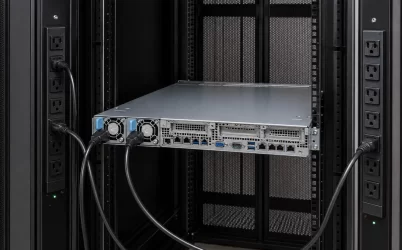
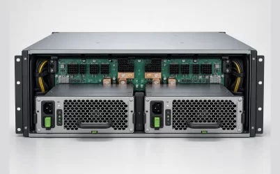
A server dual power supply setup can keep a machine running after one PSU fails, but only when the server is configured for redundancy and the remaining PSU can carry the entire protected load. Two modules in two bays do not prove that result. The pair may be operating as 1+1, where either unit can support the server, or as 2+0, where both units are needed for capacity. The cords may also lead to the same upstream source, leaving one shared point of failure outside the chassis.
The useful question is simple: if PSU A, its cord, or its rack feed disappears, can PSU B support the required workload by itself? This article answers that question directly. It explains what two PSUs can protect, what they cannot protect, and why the load at the moment of failure matters as much as the wattage printed on each module.
Quick answer: two PSUs protect only defined failures
In a supported 1+1 configuration, two power supplies can protect against the loss of one PSU module. If each module has an independent input path and the server is designed accordingly, the pair may also protect against one cord or one rack power feed failing. The server continues on the surviving side, usually with an alarm and no remaining PSU redundancy until the failed side is restored.
That protection has clear limits. Two PSUs do not automatically cover a failed power distribution board, motherboard power fault, common UPS, common rack PDU, shared branch circuit, or facility outage. They also do not protect a workload that requires more power than one surviving PSU can provide. In those cases, the server may reduce performance, power-cap the workload, or shut down. The exact response is platform-specific.
Even the operating mode must be checked rather than inferred. Dell’s PowerEdge R540 installation and service manual, for example, states that two identical PSUs can be configured in BIOS as either 1+1 with redundancy or 2+0 without redundancy. That is a platform-specific example, but the lesson is general: count the supported capacity after a failure, not the number of handles at the rear of the server.
What the common two-PSU arrangements mean
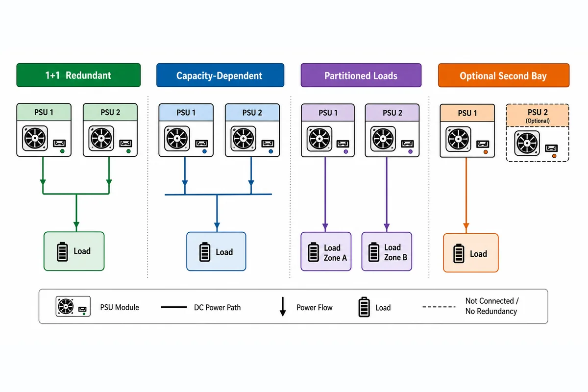
The same physical layout can produce different outcomes. A server may share the normal load across both PSUs, or it may keep one unit in a low-power hot-spare state. Either policy can still be redundant if the awake or surviving module can assume the full required load. Conversely, equal load sharing does not prove redundancy. It may simply mean that both supplies are contributing because neither can support the load alone.
| Installed arrangement | What happens in normal operation | What happens if one PSU is lost |
|---|---|---|
| One installed PSU | One module carries the server | The server normally loses power; there is no PSU redundancy |
| Two PSUs in supported 1+1 mode | The load may be shared, or one module may act as a hot spare | The surviving PSU carries the protected load if it has enough available output |
| Two PSUs in 2+0 or combined-capacity mode | Both modules are required to meet the configured power demand | Capacity falls below the requirement; continued full operation is not protected |
| Two redundant PSUs on one upstream source | The server has two conversion modules but one shared input path | One PSU fault may be covered, but failure of the shared source can stop both |
| Two redundant PSUs on independent A/B paths | Each module receives power from a different rack path | One module, cord, or defined feed failure may be covered, subject to surviving capacity |
The word supported matters. Matching wattage alone does not make two modules a valid pair. The server vendor may require identical PSU types, supported part families, particular firmware, and a specific BIOS or management setting. A mismatched unit may power up without participating in redundancy, or the server may report the whole pair as non-redundant.
The 1200W example: 900W can survive, 1500W cannot
Consider a hypothetical server with two 1200W power supplies. Assume the chassis supports both modules, the redundancy mode is correctly configured, and each PSU can actually deliver 1200W under the installed AC-input and temperature conditions. Also assume that the numbers below describe DC power required by the server, so they are being compared with PSU output capacity rather than wall-input power.
At a 900W server load, one 1200W PSU has 300W of output margin. During normal operation, the system may divide the load between the modules, roughly 450W each, or it may let one PSU carry most of the load while the other waits in a hot-spare state. If either PSU is lost, the remaining unit can take the 900W demand because 900W is below its available 1200W output. The server can therefore remain online after that single failure, provided the transfer behavior and the rest of the power path are working as designed.
At a 1500W load, the same pair tells a different story. Both PSUs together may be able to run the server if the platform permits combined-capacity operation, but one 1200W survivor cannot maintain a 1500W demand. The shortfall is 300W. After one module is lost, the platform must reduce demand, limit performance, shed some load, or shut down. Which action occurs depends on the server’s power controls; it should not be guessed. What is certain is that 1500W of full-load operation is not protected by one 1200W survivor.
This is why adding the two nameplates can be misleading. “Two 1200W PSUs” describes up to 2400W of installed converter capacity under qualifying conditions. It does not mean that 2400W is redundant capacity. For a 1+1 pair, the protected power ceiling is normally set by one module’s available output, not by the sum of both modules.
A/B feeds extend protection beyond the module
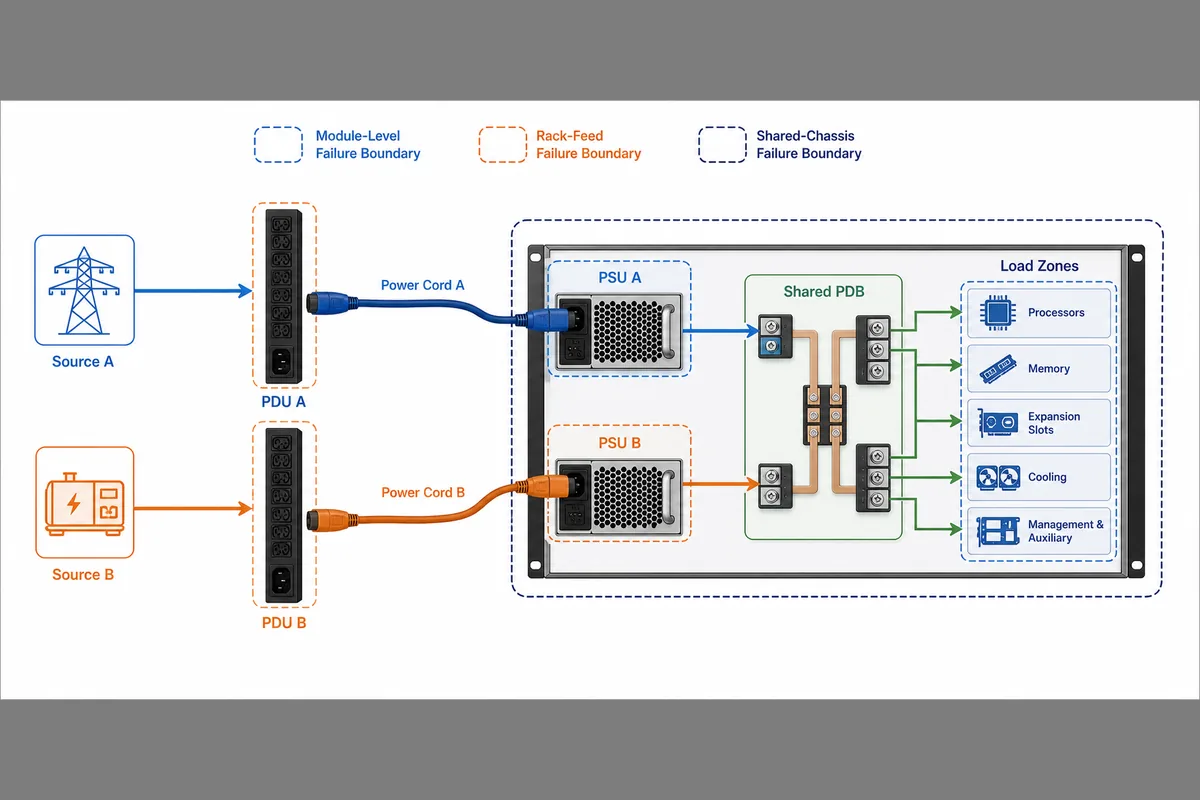
Two correctly configured PSUs can still share the same external failure. If both cords plug into one rack PDU, one UPS output, or one branch circuit, the server may survive an internal PSU failure but lose both inputs when that shared source goes down. Moving the cords to different sockets on the same PDU does not remove that common point.
A stronger arrangement connects PSU A and PSU B to separate rack power paths. Depending on the site design, those paths may use different rack PDUs, branch circuits, UPS systems, or facility sources. Independence is not all-or-nothing: the paths may remain separate at the rack but meet at a shared switchboard or generator. The dual-PSU server protects only up to the first shared component.
For most server owners, the plain-language distinction is enough. Two modules on one feed can protect against some module faults. Two supported modules on separate feeds can also protect against the defined loss of one input path. Neither arrangement promises protection against every upstream outage.
What a dual-PSU server does and does not cover
The table below separates common events without treating all of them as the same “power failure.” The result always assumes that the surviving path is healthy, supported, and large enough for the active workload.
| Failure event | The server can continue when | The server is still at risk when |
|---|---|---|
| One PSU module fails | The pair is in redundant mode and one PSU can carry the load | Both PSUs are required for capacity, or the fault affects the shared output path |
| One power cord is unplugged | Each PSU has a live input and the remaining PSU can take over | Both cords feed one required external device that has also failed |
| One rack PDU or branch circuit fails | The two PSU inputs are on genuinely separate A/B paths | Both inputs are connected to the failed path |
| Server PDB or shared DC bus fails | Only if the platform has additional documented isolation beyond the PSU pair | The failed component is common to both PSU outputs |
| Motherboard, VRM, or workload fault occurs | Another system-level protection handles that separate failure | Two PSUs are the only redundancy provided |
| Both upstream paths lose power | A separate UPS or facility design keeps at least one input alive | Neither PSU receives usable input power |
A PSU pair also cannot correct the wrong replacement part, blocked airflow, a firmware mismatch, or an unsafe service procedure. Those problems may create a new failure even though the original architecture was redundant. Two power modules are one layer of availability, not a substitute for compatibility, cooling, upstream power design, or workload recovery.
Hot-swap and redundancy answer different questions
Hot-swap means a platform permits a PSU to be removed and replaced while the server is energized, under stated conditions. Redundancy means the remaining path can keep the required load running after the other path is lost. A server may have a hot-plug bay but no safe live-service margin at its present load. It may also continue running after a fault yet prohibit removal until a specified procedure is followed.
Before touching a live module, the operator should use the service instructions for the exact server model. The important facts are whether redundancy is currently healthy, which PSU has failed, whether the surviving unit has sufficient capacity, and whether the platform authorizes replacement in that state. A lit server is not by itself proof that live removal is safe.
Read the server status in plain language
Management interfaces use different labels, but the essential states are straightforward. Redundant means the configured protection is presently available. Degraded or redundancy lost usually means the server is still running but another relevant failure may stop it. Non-redundant means the installed configuration or current power demand does not meet the platform’s redundancy requirement. Restored should mean the server recognizes the complete supported pair and reports the intended redundant mode again, not merely that a replacement module is physically present.
The exact alarm wording and recovery behavior belong to the server model, so the host’s own management record has the final word. For a detailed method that follows each fault from rack feed through the server and covers commissioning evidence, see Rack Server Redundant Power Supply: Failure-Path Design. This article stays with the simpler decision: what remains powered after one side is gone?
The practical conclusion
Two PSUs are useful when the server is designed to use them redundantly, the surviving module can support the required load, and the input paths match the failure you want to cover. In the hypothetical 1200W pair, a 900W load can fit on one surviving PSU; a 1500W load cannot. Separate A/B feeds can extend protection to one cord or rack-feed failure, while shared components still define where that protection ends.
So do not ask only whether the server has dual power supplies. Ask what mode it is in, how many watts one surviving path can deliver under the real operating conditions, and where the two input paths first come together. Those three answers reveal what the server can survive—and what it cannot—without turning a pair of PSU handles into a promise the system was never designed to make.