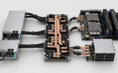
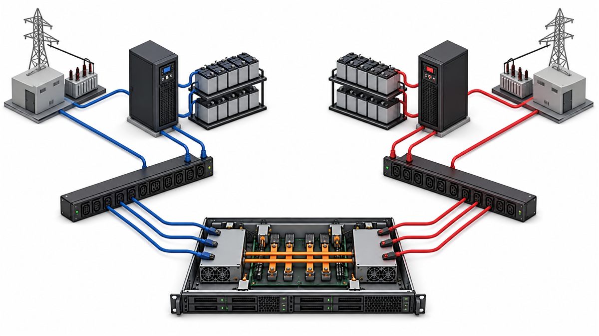
A rack server redundant power supply protects workload continuity only when the remaining power path can carry the server and the upstream feeds do not hide an unwanted common failure. The familiar pair of rear PSU modules is therefore the visible end of a larger architecture: facility source, branch circuit, rack PDU, cord, PSU, isolation stage, distribution board, and server load. This article follows failure events through that chain. Its purpose is to help an operator state exactly what the rack server will survive, how long it can remain degraded, and what evidence is needed before live service is allowed.
Begin with the outage the design must survive
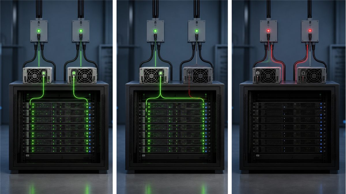
A module failure, power-cord disconnection, rack PDU outage, branch-circuit trip, UPS maintenance event, and facility-source loss are different events. A server with two modules connected to one PDU can continue after certain PSU faults yet shut down when that PDU loses power. Calling both arrangements “redundant” without naming the protected event creates a misleading availability expectation.
Draw two columns, A and B, from the facility to the server. Place every component in its real path and circle anything shared. The shared DC bus and server motherboard will remain common by design; a shared branch breaker may be an avoidable weakness. This failure-domain map is more informative than counting power cords.
What happens when PSU A disappears?
Before the event, two active modules may share current. When PSU A loses input or is removed, PSU B must take the full DC demand quickly enough that the downstream converters remain inside their input limits. The distribution board must prevent reverse current into the failed module. The BMC should record loss of input or module health, raise a loss-of-redundancy alert, and identify the correct bay.
The electrical transition can occur faster than ordinary telemetry sampling. Oscilloscope measurements of the main bus and module currents are therefore useful during platform qualification. The acceptance criterion comes from the system bus limits, not an assumption that “no interruption” means a mathematically flat waveform.
The survivor sets the server’s redundant power ceiling
For 1+1 operation, one module must support the maximum permitted server load. Use the module’s available output at the actual AC input, inlet temperature, altitude, and airflow. High-power supplies may derate at lower input voltage. An empty bay can alter airflow, while the remaining PSU produces more heat and may run its fan faster.
Workload excursions also count. CPU turbo states, GPU power changes, fan ramp, and drive activity may produce peaks that are not visible in a slow average. Establish a sustained limit and a transient envelope. If supported system firmware applies a power cap after redundancy is lost, its response time and guaranteed load reduction should be part of the platform evidence.
1+1, N+1, and input redundancy solve different capacity problems
| Mode | Capacity rule | Typical protected event |
|---|---|---|
| 1+1 | Either of two modules carries the allowed load | One module or associated path fails |
| N+1 | N modules carry the load; one extra module provides reserve | Loss of one module in a multi-module platform |
| Input redundancy | Required capacity remains after one source group is lost | Failure of an A or B feed group |
The notation describes capacity, not every failure mode. A shorted output needs isolation; a failed PDB may affect all modules; a shared cooling fault can defeat electrical reserve. The architecture statement should pair the capacity notation with its protected fault set.
A/B feeds must remain separate in everyday operations
Independent design can be undone by routine rack work. Both cords may be moved to one PDU because it has open receptacles, or both rack PDUs may be connected to the same upstream circuit. Use consistent color coding, labels at both cable ends, current monitoring, and an updated rack diagram. Periodic audits should identify dual-cord devices that are no longer split across feeds.
Load balance at the facility is another consideration. Some server power-management modes place most normal load on one PSU, which can unbalance A and B circuits even though redundant capacity exists. Platform documentation may offer policies for load sharing or hot-spare operation. Facility current alarms should account for the chosen policy and for the sudden transfer that occurs after one feed is lost.
Output isolation contains an internal PSU fault
When modules join a common bus, a shorted or unpowered output must not become a load on the healthy source. ORing diodes or controlled MOSFET stages provide reverse-current blocking in many designs. Their location may be inside the PSU, on the PDB, or distributed between them. The devices add resistance and thermal stress, especially when a single path carries full current.
Qualification should include the supported fault conditions and recovery behavior. Protection functions such as overcurrent, overvoltage, overtemperature, and fan fault have thresholds, timing, and latching policies that vary by model. A generic list of protection abbreviations does not establish how a redundant pair behaves during a fault.
Loss of redundancy is an operational incident
The server may continue normally after one path fails, which makes alerting essential. Local indicators help an onsite technician; remote BMC and monitoring alerts support timely response. The alert should distinguish missing input, removed module, internal fault, fan problem, and management communication loss where the platform exposes those states.
Define a repair objective based on business risk and the thermal capability of the degraded state. The server is now one failure away from outage. Keep approved spares, ensure access to the correct rack, and provide a service instruction that names the bay and feed. Do not wait for a maintenance window by habit if the availability policy requires faster restoration.
Efficiency policies can move load between A and B
Keeping two modules active at light server load can place each in a less favorable part of its efficiency curve. Some supported platforms respond with a hot-spare or efficiency policy that places most output on one module while the other remains ready. This can reduce conversion loss, but it also shifts normal rack current toward one feed. Capacity planners should examine the PDU and branch readings produced by the selected policy rather than assuming an even split.
A source failure can then transfer substantial current to the other side in a short interval. The receiving PDU, branch, UPS path, cord, and PSU must have enough headroom. If many servers in one rack use the same preferred side, their transfers can coincide. Alternating preference or using a platform-supported rotation policy may improve facility balance, subject to the server vendor’s guidance.
Hot replacement depends on the entire interface
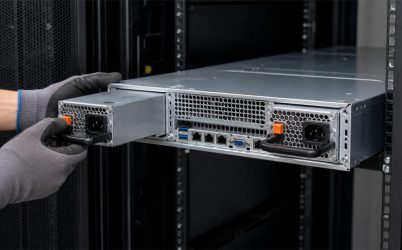
A module may be physically removable yet not approved for live replacement. True hot swap coordinates connector contact lengths, precharge or presence, inrush limiting, enable, power-good, isolation, and BMC state. Before extraction, the operator must identify the failed module and confirm that the healthy path supports the current workload.
After insertion, the replacement should be recognized, enter the correct power state, join current sharing, and clear only the appropriate alarms. A visually similar or higher-wattage module may have a different connector, pinout, management identity, airflow direction, or sharing behavior. Use the server’s approved part information or perform a complete platform qualification.
Test the rack server as it will be deployed
- Run the production configuration at idle, typical, and maximum allowed workload.
- Record the contribution, input, temperature, and fan behavior of each PSU.
- Interrupt feed A, then restore it and confirm sharing and alarm clearance.
- Repeat for feed B without changing workload conditions.
- Remove and insert each module under the documented hot-swap procedure.
- Observe the main bus during transitions and inspect BMC telemetry and event logs.
- Hold maximum redundant load on one module until temperatures stabilize.
- Confirm that rack PDU and branch capacity tolerate the transferred load.
Run critical tests after changes to PSU revision, PDB, BMC firmware, chassis airflow, accelerator configuration, or facility input. A validated limit belongs to a configuration, not merely a product family name.
Common rack failures that redundancy does not automatically cover
A single PDB, motherboard fault, misconfigured power cap, blocked airflow path, or operator error can affect both modules. So can a common upstream transfer switch or maintenance bypass. Redundancy reduces selected failure risk; it does not make the server immune to every outage. Good availability design combines independent paths with monitoring, controlled change, spares, and tested recovery.
Rack cable management creates another shared risk. A tight bundle can place mechanical load on both inlet connectors, while a rear-door obstruction can restrict the exhaust from both modules. During inspection, look beyond electrical diagrams: verify cord retention, bend radius, PDU receptacle security, exhaust clearance, and access to each latch. Physical arrangement often determines whether a designed independent path remains independent during service.
For module-to-PDB design detail, use the CRPS redundant power supply integration guide. Powernexu’s dual redundant server power architecture article provides a complementary explanation of current sharing and degraded capacity.
Operational questions
Do both server PSUs normally carry half the load?
Many active-sharing systems divide current approximately, but the balance is not perfect and some platforms use an efficiency or hot-spare mode. The exact policy depends on compatible PSU, PDB, and firmware behavior.
Can both modules be plugged into one UPS?
Yes when the intended protection is limited, but that UPS becomes a common failure point. If the requirement includes loss of an upstream source, use an appropriately independent A/B design.
Why does the rack PDU need spare capacity?
After one feed fails, the surviving PDU or branch receives the transferred load. It must support that condition without overload. Normal balanced current can hide insufficient failover capacity.
Can different wattage modules be mixed?
Only when the server vendor explicitly supports the pair or engineering qualification demonstrates correct electrical, thermal, sharing, firmware, management, and fault behavior. Matching output voltage is insufficient.