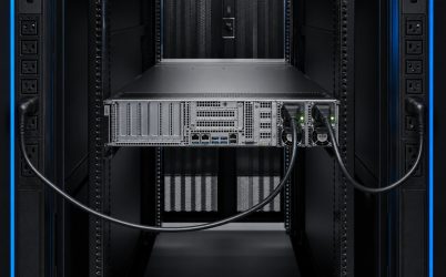
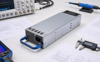
A server power supply distribution board, commonly called a PDB, is the electrical and mechanical bridge between removable PSU modules and the server’s loads. It can carry hundreds of amperes on low-voltage rails while also routing standby power, enable, power-good, current-share, present, fault, sense, and management signals. In redundant systems it may provide output isolation and hot-swap coordination. Successful PDB design therefore depends on current-path resistance, connector integrity, fault behavior, timing, telemetry, thermal management, mechanical tolerance, and compatibility with both the PSU and downstream system.
Quick answer: design and validate the complete current path
Start with normal, transient, and single-PSU current for every rail. Map current from each PSU contact through connectors, copper, vias, ORing devices, shunts, fuses, busbars, and downstream outputs. Budget voltage drop and heat at each interface. Then define exact signal pinouts, mating sequence, standby behavior, current sharing, PMBus routing, fault isolation, and mechanical datums. Validate at input and temperature extremes with production PSUs, chassis airflow, cables, loads, and BMC firmware. A PDB is ready only when electrical, thermal, mechanical, service, and management behavior have been proven together.
Translate server demand into current paths
Build a rail-by-rail load profile that includes idle, typical, sustained maximum, startup, and fast transients. Low-voltage, high-power distribution produces high current, so small resistances matter. For a hypothetical 12 V bus carrying 100 A, only 1 milliohm produces a 0.1 V drop and 10 W of heat. This example shows why connector contacts, copper transitions, shunts, and joints deserve close attention; it is not a rating for a particular board.
In a redundant design, calculate both normal sharing and the state after one PSU is removed. The surviving path can carry approximately twice its normal current in a balanced 1+1 system. Downstream branches may also experience unequal loading based on cable and connector resistance. Use worst-case component tolerances and temperature coefficients rather than a nominal schematic alone.
Budget voltage drop from source to load
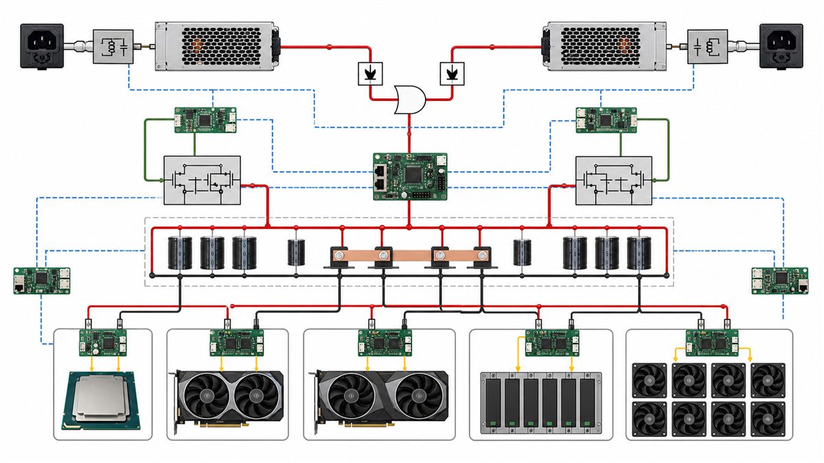
Allocate an allowable drop to each segment: PSU connector, PDB copper, isolation stage, current sensor, branch protection, output connector, cable, and downstream board interface. Remote sense may compensate for part of the path, but sense range is limited and the pickup location determines what is regulated. Incorrect sense routing can cause circulating current, unstable sharing, or excessive voltage at another point.
Measure drop at operating temperature because copper and contact resistance rise as temperature increases. Four-wire measurements are useful for low resistance, while an oscilloscope captures dynamic deviation during rapid load steps. Compare measurements at each branch so a local high-resistance connection is not hidden by an acceptable bus reading elsewhere.
Size copper, vias, and busbars for heat as well as current
Trace width calculators provide a starting point, but dense server boards include planes, cutouts, vias, connectors, and components that create three-dimensional heat flow. Parallel layers need enough stitching, and current should transfer between layers without concentrated bottlenecks. Busbars can reduce resistance for very high current but introduce mechanical, assembly, insulation, and tolerance requirements.
Current density near connector footprints and ORing devices is often less uniform than expected. Simulation can identify risk areas, but thermal-camera and thermocouple measurements on representative hardware remain important. Include manufacturing tolerances such as copper thickness, plating, solder voids, fastener torque, and interface flatness where they affect performance.
Blind-mate connectors combine power and sequencing
The PSU connector must align across chassis and board tolerances, engage fully, and carry current per contact without excessive temperature rise. Contact length may sequence chassis ground, returns, presence, precharge, signals, and main power. Exact assignments and mating order come from the interface documentation. Never copy a footprint or pinout from a visually similar module.
Connector current ratings depend on contact count, temperature, airflow, wire or copper termination, and whether adjacent contacts are energized. Derating can be significant. Unequal contact resistance can overload individual pins even when total current appears acceptable. Inspection and qualification should verify alignment, wipe, insertion force, retention, plating condition, and temperature after repeated service cycles.
ORing isolates a failed module from the shared bus
Redundant PSU outputs need reverse-current blocking so an unpowered or faulted module does not sink current from the healthy source. Diodes offer simple behavior but add forward drop and loss. MOSFET-based ideal-ORing can reduce loss but requires control, gate protection, stability, and fault analysis. The function may reside in the PSU, PDB, or a coordinated combination, so the boundary must be explicit.
Review shorted devices, open devices, controller loss, reverse input, and hot insertion. Ensure the isolation stage can survive and interrupt credible faults without violating the server bus. Protection coordination with PSU current limiting and downstream branch protection should prevent one fault from taking down both redundant paths.
Hot swap requires controlled inrush and contact order
When a live module is inserted, discharged capacitors can draw a large current. Precharge contacts, inrush limiting, soft start, or hot-swap controllers may manage the event. The healthy PSU must keep the shared bus within tolerance while the new module initializes. During removal, the connector should disengage in the intended order without arcing beyond its rating or leaving control inputs in unsafe states.
Capture the shared bus, incoming-module current, enable, power-good, and relevant status signals during insertion and extraction. Test both bays at several loads and temperatures. Repetition helps expose contact bounce, thermal effects, or timing variation that a single demonstration may miss.
Standby and control signals define power-state behavior
The PDB may route standby output to the BMC before the main rail is enabled. It can combine or isolate power-good, present, fault, and enable signals and carry current-share and remote-sense connections. Logic voltage, polarity, pull-up location, default state, and timing must match both PSU and host. A naming similarity is not enough.
Analyze power-off, AC insertion, standby, main-rail startup, normal operation, input loss, PSU fault, hot removal, and shutdown. For every state, define which rails and signals are valid and what the BMC should report. Avoid backfeeding an unpowered domain through signal protection or communication lines.
PMBus routing must remain reliable with two modules
Management buses connect electrically simple signals to operationally complex behavior. Verify addressing, pull-ups, voltage domain, isolation if used, capacitance, layout, connector sequencing, and recovery from a stuck or absent device. Each PSU should be uniquely identified without conflict, and replacing one module should not disrupt communication with the other.
Host firmware may depend on manufacturer data, telemetry scaling, supported commands, and fault bits. Build a command-and-state matrix for the exact modules. Compare telemetry with external instruments if the values will be used for power caps or capacity management. A PDB that distributes power correctly can still fail platform acceptance through its management path.
Thermal validation should target interfaces
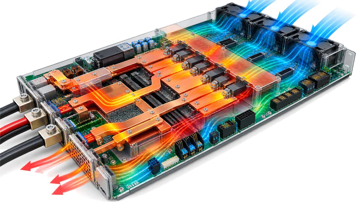
The hottest locations are often transitions rather than broad copper areas: connector contacts, vias, shunts, ORing devices, fuses, fasteners, and cable terminations. Airflow can bypass components or be blocked by cables. Measure temperatures at sustained maximum load and after one PSU is removed, when current and airflow change.
Use the production enclosure, fan policy, blanking pieces, PSU airflow direction, and nearby heat sources. Evaluate high inlet temperature and altitude where required. Thermal limits should include component ratings, connector derating, PCB material, solder joints, cable insulation, and service-life objectives. A thermal image is helpful, but attached sensors may be needed where emissivity or line of sight makes imaging unreliable.
Mechanical design protects connector engagement
The chassis, guides, PSU latch, PDB mount, and connector float determine alignment. Tolerance stack-up should permit insertion without using the connector to force the module into position. Board flex, vibration, cable force, and thermal expansion must not unload contacts. Provide extraction clearance and support so service does not stress the PDB.
Downstream cable routing should avoid fan blockage, sharp bends, abrasion, and excessive connector load. Key and label outputs to reduce assembly errors. If high-current fasteners are used, define hardware, surface preparation, torque, locking method, and inspection. Mechanical work instructions are part of electrical reliability.
Protection should localize downstream faults
A short on one branch should be prevented from damaging the PDB or collapsing unrelated loads when the architecture requires branch isolation. Fuses, electronic protection, current monitoring, or downstream converters may participate. Coordinate their trip behavior with PSU current limiting and the energy stored in bulk capacitance. Protection components need adequate interrupting and thermal capability.
Fault injection should be planned safely. Verify overcurrent response, short-circuit behavior, open sense, missing PSU, communication fault, fan fault, and input loss as applicable. Observe both electrical response and BMC reporting. Document whether recovery is automatic, latched, or requires service.
A practical PDB qualification sequence
- Audit schematic, layout, pinout, tolerance stack, and interface documents.
- Measure low-resistance paths and verify connector engagement before full power.
- Start at controlled current and check rail, signal, standby, and PMBus behavior.
- Exercise startup, shutdown, dynamic load, and input extremes.
- Run sustained thermal tests in normal sharing and single-module states.
- Remove and insert each PSU while monitoring bus voltage, current, and signals.
- Inject defined faults and verify isolation, protection, alarms, and recovery.
- Repeat critical tests across board, PSU, firmware, and manufacturing samples.
Release records should identify the PDB revision, approved PSU models and revisions, BMC firmware, chassis configuration, connectors, cables, and test limits. Any substitution that changes these interfaces deserves review.
For a complementary selection perspective, see Powernexu’s CRPS power distribution board design and selection article. The CRPS compatibility guide can help verify the module side of the same interface.
Questions about server PDBs
Is a PDB just a breakout board?
Not in many servers. It may handle very high current, redundancy isolation, inrush, sensing, control, hot swap, standby power, telemetry routing, and fault reporting. Its exact functions are platform-specific.
Can one PDB support different PSU wattages?
Possibly, but only when electrical, thermal, mechanical, signal, management, and firmware compatibility is documented. Higher PSU capacity does not increase the PDB’s current rating automatically.
Why does a connector overheat below its total rated current?
Possible causes include uneven current sharing among contacts, partial engagement, contamination, plating damage, poor alignment, insufficient termination copper, high local ambient, or applying a rating under different conditions. Measure individual interfaces and inspect the mechanical system.
Where should remote sense connect?
At the location defined by the PSU and platform design, commonly chosen to regulate a critical bus point. Incorrect placement can overcompensate one segment or disrupt sharing. Follow exact documentation and validate open- and short-sense behavior.