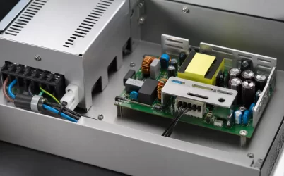
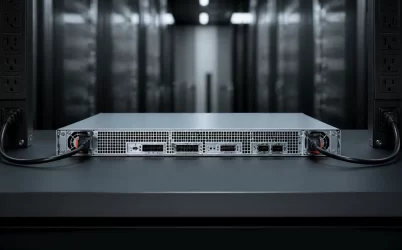
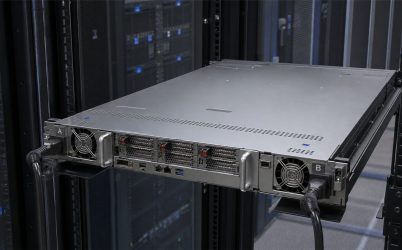
A standard CRPS power supply is a modular redundant PSU designed around a common mechanical and electrical framework for server platforms. The standardization can reduce custom engineering and simplify service, but it does not make every CRPS module interchangeable. Before substitution, engineers must verify the exact form factor, output class, input range, blind-mate connector implementation, signaling, PMBus behavior, airflow, firmware expectations, and chassis qualification. Compatibility is a system property shared by the PSU, cage, power distribution board, BMC, and cooling design.
Quick Answer
Use a standard CRPS power supply when a server needs compact hot-swap redundancy and a repeatable module interface. Select the module by the applicable CRPS or M-CRPS specification revision and the platform’s own supported-module list. Matching dimensions and wattage are necessary but insufficient. Confirm connector mating, output voltage, standby rail, enable and presence signals, current sharing, fault isolation, PMBus commands and addressing, airflow direction, acoustic behavior, and rated output under the deployed AC input and temperature.
What “Standard CRPS” Actually Standardizes
CRPS commonly refers to a Common Redundant Power Supply approach used in rack, storage, enterprise, edge, and high-performance systems. A common framework can define envelopes, insertion behavior, connector regions, electrical expectations, management interfaces, and environmental requirements. The OCP DC-MHS M-CRPS work extends this objective by defining power-supply solutions and signaling intended for modular hardware systems.
Standards improve the probability that modules and platforms can share infrastructure. They do not remove implementation choices. A vendor may support different output ratings, input ranges, airflow directions, temperature classes, management functions, firmware policies, or optional signals within related mechanical families. The server manufacturer’s qualification remains decisive.
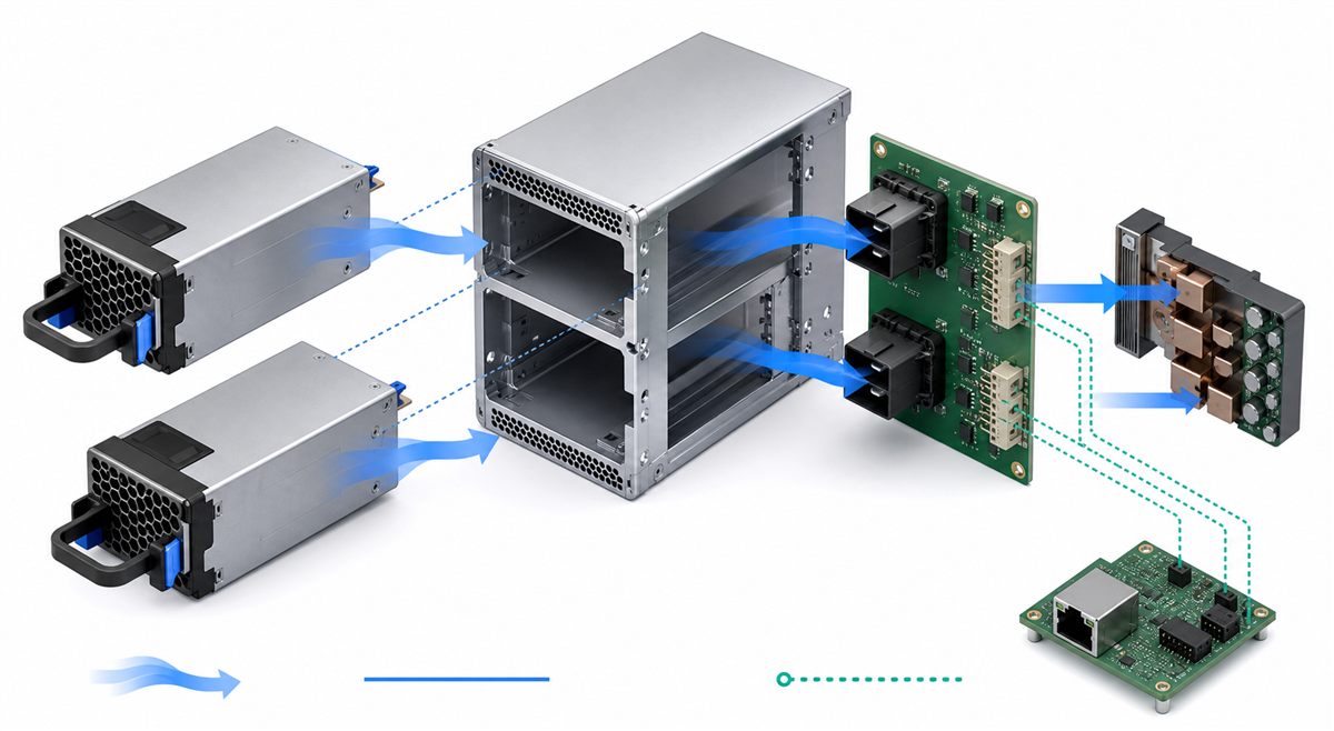
Six Compatibility Layers to Check
| Layer | Required verification |
|---|---|
| Mechanical | Envelope, insertion depth, latch, handle, cage rails, connector alignment, and keep-out zones |
| Power | AC range, DC output, standby supply, available power, current limit, and derating |
| Connector | Approved mating pair, contact sequencing, current capability, keying, and insertion life |
| Control | Enable, present, power-good, fault, current-share, and address signals |
| Management | PMBus/SMBus support, FRU information, telemetry units, firmware, and BMC policies |
| Thermal | Airflow direction, fan curve, impedance, inlet temperature, altitude, and acoustic limits |
A mismatch in any layer can prevent startup, create poor current sharing, produce false alarms, reduce available capacity, or overheat a connector even when the module slides into the cage.
Redundancy Changes the Required Wattage
Suppose a server requires a maximum sustained 1,450 W DC and the design target adds 10% capacity for qualified configuration growth. The required capacity is 1,595 W. In a 1+1 system, each module must independently support at least 1,595 W under the real AC input and thermal conditions. Two 1,600 W modules provide redundancy with only a narrow nameplate margin; they do not provide 3,200 W of redundant capacity.
If the same load is shared by three modules in a 2+1 arrangement, each surviving module would need to support at least 797.5 W, assuming two modules carry the full required load after one failure. Current sharing, transient behavior, and the platform’s permitted operating modes still need validation.
PMBus and BMC Integration
Management compatibility affects more than dashboard visibility. A BMC may use PSU identification, input and output telemetry, temperature, fan speed, status words, fault history, and redundancy state to make cooling or workload decisions. Address selection must prevent bus conflicts in a multi-PSU system. FRU data should identify the installed module consistently, and unsupported commands should fail in a controlled way.
Do not assume that two modules using PMBus expose identical commands, scaling, timing, or firmware behavior. Test the exact PSU and BMC firmware combination, including boot, standby, hot insertion, fault, and recovery states.
Airflow and Derating
Compact CRPS modules operate at high power density. Their usable output depends on how much air the chassis can move through the module and on the temperature of that inlet air. A module rated at one laboratory condition may require derating at a lower AC input, higher temperature, altitude, or restricted airflow.
For a hypothetical 1,600 W output at 93% efficiency, input power is about 1,720 W and conversion loss is about 120 W. That heat is concentrated in a narrow enclosure. Small changes in fan control, recirculation, or blockage can raise component and connector temperatures, so chassis testing is mandatory.
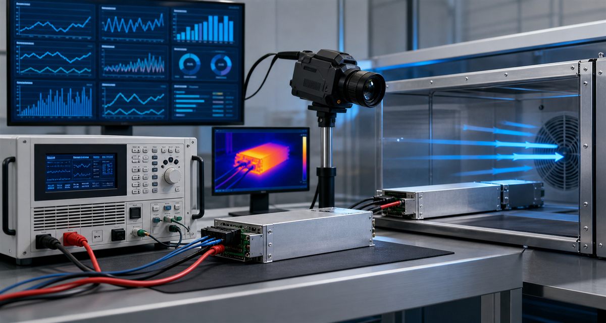
A Practical Qualification Process
- Freeze the applicable specification revision and platform requirements.
- Inspect mechanical fit and connector engagement before powered tests.
- Verify standby, startup, enable, power-good, and fault sequencing.
- Load each module across the expected range and confirm current sharing.
- Remove and insert modules at representative loads while monitoring the DC bus.
- Test loss and restoration of each AC feed.
- Validate PMBus telemetry, addressing, FRU data, alarms, and BMC event logs.
- Repeat at worst-case input voltage, inlet temperature, airflow, and altitude conditions.
See CRPS redundant power supply integration and qualification for a deeper treatment of system validation. A standard interface reduces integration effort only when every relevant option and condition is checked.