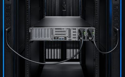
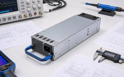
An industrial DC power supply provides regulated direct-current power for equipment that must operate through electrical noise, temperature variation, mechanical stress, and long service cycles. Selecting one requires more than matching the nominal voltage and wattage. The supply must accept the actual source, support steady and transient loads, remain within its thermal limits, coordinate with wiring and protection devices, and recover predictably after faults. For an industrial control cabinet, machine, telecom enclosure, test system, or embedded computer, the best candidate is the unit whose documented operating envelope matches the finished installation—not simply the unit with the largest number on its label.
Quick answer: define the electrical and environmental envelope first
Begin with minimum and maximum input voltage, required DC rail, continuous load, startup and pulse currents, ambient temperature, altitude, cooling, mounting method, and applicable safety or EMC requirements. Then check derating curves, overload behavior, hold-up or ride-through needs, ripple, isolation, protection functions, and mechanical clearances. If uptime is critical, define the redundancy architecture and the load that one surviving supply must carry. Finally, validate the selected unit in the production enclosure at input, load, and temperature extremes. This sequence prevents a supply that looks adequate on paper from causing resets, nuisance shutdowns, or excessive heat in service.
Characterize the source before choosing a converter
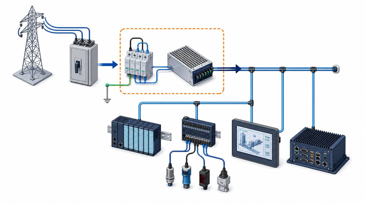
The phrase “industrial input” can describe very different conditions. A factory cabinet may receive nominal AC mains with switching transients from nearby motors. A vehicle or battery-backed system may present a wide DC range that moves with charging state. A telecom installation may use a negative DC bus. A generator or UPS can add waveform and transfer behavior that does not appear in a simple nominal-voltage specification. Record the normal range, expected dips, surges, interruptions, frequency where applicable, grounding arrangement, and source impedance. The power supply documentation must explicitly support those conditions.
Input protection also belongs to the system design. A supply may contain internal fusing, surge suppression, and inrush limiting, but those features do not automatically satisfy branch protection, disconnect, coordination, or installation-code requirements. Upstream breakers or fuses should suit conductor size, available fault current, and the supply’s input behavior. If several supplies start together, their combined inrush can trip an otherwise correctly sized branch device. Sequencing, staged energization, or a different protective device characteristic may be needed, subject to applicable safety rules.
Build a load profile instead of using one current value
A useful load schedule separates continuous demand from events. Controllers, sensors, network devices, and indicator circuits may be relatively stable. Solenoids, relays, valves, fans, pumps, heaters, capacitive input stages, and industrial computers can create startup or step loads. For each branch, document normal current, credible maximum, peak magnitude, duration, repetition rate, and whether multiple branches can peak simultaneously. The combined result is a time-based profile rather than a single average.
That distinction matters because overload specifications vary. Some supplies provide a short boost above continuous rating; others enter constant-current, foldback, hiccup, or shutdown behavior. A motor-start pulse that is acceptable to one design may pull another supply into a restart cycle. Review the manufacturer’s overload curve and recovery description. If the documentation does not define the duration and conditions of peak capability, do not assume that a higher instantaneous load is supported.
Voltage at the power-supply terminals is not necessarily voltage at the load. Long conductors, connectors, fuses, relays, and distribution blocks add resistance. Estimate the drop at maximum branch current and confirm it by measurement. Remote sense can compensate for some distribution loss when supported, but sense leads must be routed and protected as specified; compensation range is limited, and an open sense wire can create abnormal behavior unless the design handles it safely.
Use derating curves to find usable power
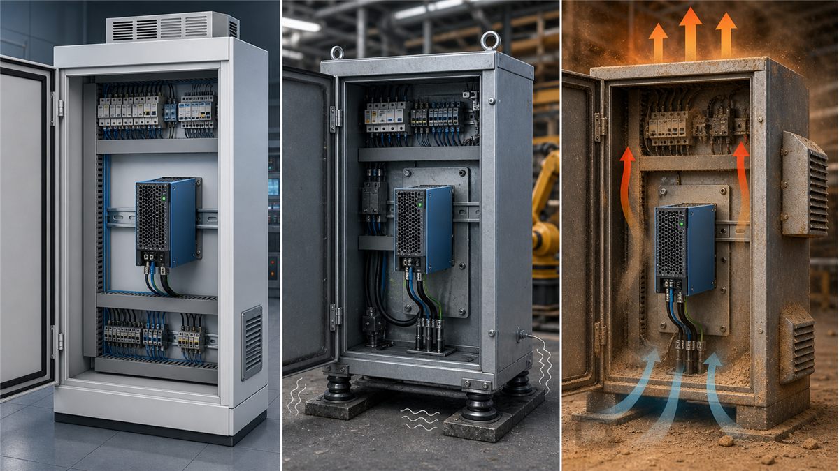
Industrial enclosures often run much hotter than the surrounding room. The temperature that matters is the supply’s specified measurement condition—commonly the local ambient or inlet temperature—not the building thermostat. Heat from drives, processors, contactors, and neighboring supplies can raise that value considerably. Evaluate the published derating curve at the expected worst-case temperature, airflow, input voltage, and altitude. A nominal 500 W unit may have less usable output under a particular high-temperature or low-line condition.
Cooling method changes integration requirements. A fan-cooled supply needs a defined airflow path, clean inlet area, and enough clearance to prevent recirculation. A conduction-cooled or baseplate-cooled unit needs a controlled thermal interface to a suitable surface. A fanless open-frame unit still releases heat into the enclosure and depends on orientation, spacing, and natural or forced convection. “Fanless” should not be interpreted as “no thermal design required.”
Account for contamination, vibration, and service access
Dust can insulate hot components or block airflow. Conductive particles, moisture, condensation, oil mist, and corrosive gases can create leakage or corrosion. Vibration and shock can stress heavy components, solder joints, terminal blocks, and mounting hardware. The appropriate response may involve an enclosed supply, conformal coating, filtered ventilation, sealed cabinet, different connector system, or a supply qualified for the mechanical environment. These choices must be based on documented ratings and the enclosure strategy rather than visual appearance.
Maintenance needs affect layout. Leave access for terminal screws, connectors, fuses, status indicators, and removal hardware. Observe minimum clearances and keep hazardous-voltage wiring separated from low-voltage control wiring as required. Label branch circuits so a technician can isolate the correct load. If replacement time matters, standardize mounting and connectors while preventing an incompatible unit from being inserted accidentally.
Interpret ripple, regulation, and dynamic response in context
Output accuracy has several components: initial set-point tolerance, line regulation, load regulation, ripple and noise, temperature drift, and transient deviation. A sensor or communication circuit may be sensitive to high-frequency noise, while a processor can reset during a short voltage dip caused by a rapid load step. Compare the load’s permitted voltage envelope with the supply’s documented performance under the intended wiring and capacitance. Measurement technique matters; a long oscilloscope ground lead can display noise that is largely a probing artifact.
Adding large external capacitance is not automatically a cure. It can increase startup energy, interact with current limiting, extend discharge time, and change control-loop behavior. Confirm the permitted capacitive load and any minimum-load requirements. When multiple converters feed one system, also evaluate startup order, backfeeding, and whether downstream converters present negative-impedance behavior that can destabilize an upstream stage.
Protection functions must produce a safe machine state
Overvoltage, overcurrent, short-circuit, and overtemperature protection are common labels, but their thresholds, delays, latching behavior, and recovery methods differ. A hiccup-mode supply may repeatedly attempt restart. A latched shutdown may require input cycling. Constant-current behavior can keep wiring energized during a partial fault. Read the details and decide what the process should do after each event. The power supply’s internal protection does not replace correct wire sizing, branch fusing, protective earth, or load-specific protection.
For machinery and process controls, the loss and return of DC power must be considered in the risk assessment. Unexpected restart can be hazardous. Safety-related functions may require dedicated architecture and certified components; a general-purpose supply should not be assigned a safety function merely because it is reliable. Define which outputs must drop, which states must be retained, and whether operator acknowledgement is required before the machine resumes.
Design redundancy around failure domains
Two supplies connected to a common bus are not automatically redundant. Safe parallel operation may require active current sharing and output isolation through diodes or ideal-ORing devices. In a true redundant arrangement, the remaining supply must support the permitted load after one module, input feed, or distribution path fails. If both supplies share the same breaker, connector, redundancy module, or cooling path, those common elements remain single points of failure.
Redundancy can improve availability but increases component count and may alter efficiency because each module operates at a lower load fraction. Monitoring should identify a failed path promptly; otherwise a system may continue unnoticed without redundancy. Periodic tests should verify alarms, isolation, and operation on each individual path. The architecture should state whether it protects against a supply failure, source failure, branch failure, or a broader set of events.
Qualification closes the gap between datasheet and installation
A bench test at room temperature is only a starting point. Exercise minimum and maximum input, cold start, steady full load, representative load steps, repeated peak loads, brownout, recovery, and controlled faults. Measure output at the remote load, not only at the supply. Record temperature at critical locations after the enclosure reaches equilibrium. For forced-air systems, evaluate fan blockage or reduced airflow if that is a credible service condition.
EMC testing should use production-equivalent cables, filters, grounding, enclosure panels, and load activity. Changes in cable routing or earth bonding can change emissions and immunity. Check conducted disturbances, radiated behavior, electrical-fast-transient exposure, surge, and electrostatic discharge according to the product’s regulatory plan. A component approval can support system compliance, but it does not automatically certify the completed machine.
A procurement checklist that engineering can verify
- Exact input range and source characteristics, including abnormal events
- Output voltage, continuous current, peak profile, and distribution drop
- Derated capacity at maximum temperature, altitude, and minimum input
- Mechanical envelope, mounting orientation, cooling path, and service clearance
- Isolation, grounding, ripple, transient response, and capacitive-load limits
- Protection mode, restart behavior, external fusing, and safe system response
- Required approvals and the scope in which they apply
- Redundancy, current sharing, isolation, alarms, and surviving-path capacity
- Qualification evidence in the final enclosure under realistic operating states
This checklist turns “industrial grade” from a marketing description into verifiable requirements. For a broader comparison of form factors and selection factors, use Powernexu’s article on selecting an industrial power supply. If a project needs a particular mechanical package, rail arrangement, or redundant power architecture, the requirements can be shared through the Powernexu contact page for a technically grounded discussion.
Questions buyers often need to resolve
How much capacity margin should an industrial DC supply have?
There is no universal percentage. Margin should cover credible continuous load growth, component tolerances, peak behavior, thermal and low-line derating, and aging without placing normal operation in an inefficient or poorly controlled region. Derive it from the actual profile and published limits rather than applying a fixed multiplier to every application.
Can two ordinary supplies be paralleled for more current?
Only when the manufacturer supports the intended parallel arrangement or an engineered isolation and sharing design makes it safe. Small voltage differences can cause one unit to carry most of the load, and a failed output can pull down the common bus. Verify current sharing, reverse-current protection, startup, and fault isolation.
Is a higher wattage supply automatically more reliable?
No. Operating margin can be useful, but reliability also depends on component temperature, airflow, electrical stress, source disturbances, load dynamics, contamination, and installation quality. An oversized unit placed in a hot blocked enclosure can be less dependable than a correctly sized unit with a validated thermal path.
What should be measured during final validation?
At minimum, measure load-terminal voltage during startup and dynamic events, input current and inrush where relevant, enclosure and supply temperatures at worst case, fault and recovery behavior, and EMC performance required by the product plan. Redundant systems should also be tested with each path removed separately.