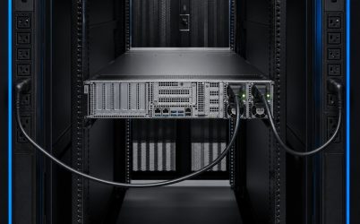
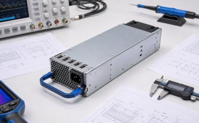
A dual redundant server power supply uses two coordinated PSU modules so the server can remain powered after a defined single-path failure. The phrase does not mean that any two installed supplies guarantee uninterrupted operation. One surviving module must support the full permitted load, the shared PDB must isolate a failed path, current sharing must remain stable, and upstream power should be separated if the design is intended to tolerate more than a PSU failure. A credible architecture therefore states its protected failure set, degraded-state capacity, hot-swap procedure, alarms, and validation evidence.
Quick answer: verify capacity, isolation, and independence
For 1+1 redundancy, confirm that either PSU can carry the server’s maximum permitted steady and transient demand at the actual input voltage, temperature, altitude, and airflow. Verify that a failed or removed module cannot pull down the common DC bus, and that the PDB, connectors, and wiring can carry the shifted current. If protection from branch or PDU failure is required, feed the two modules from appropriately independent A and B paths. Test each module and feed separately, observe rail stability and telemetry, and document the load limit that preserves redundancy.
Distinguish 1+1 redundancy from combined capacity
Two 1,200 W modules can describe different usable architectures. If the server’s permitted load is no more than the usable capacity of one module, the pair may support 1+1 redundancy. If the server needs both modules to deliver its normal load, it has combined capacity but cannot tolerate the complete loss of either module at that operating point. Marketing labels should not replace this simple surviving-capacity test.
Usable capacity is condition-dependent. A PSU may be derated at low AC input, high inlet temperature, high altitude, or restricted airflow. The survivor can also run hotter because it carries more current and because an empty PSU bay changes airflow. Define the redundant load limit with the worst supported combination, not only the nominal room-temperature rating.
Map the complete A and B power chains
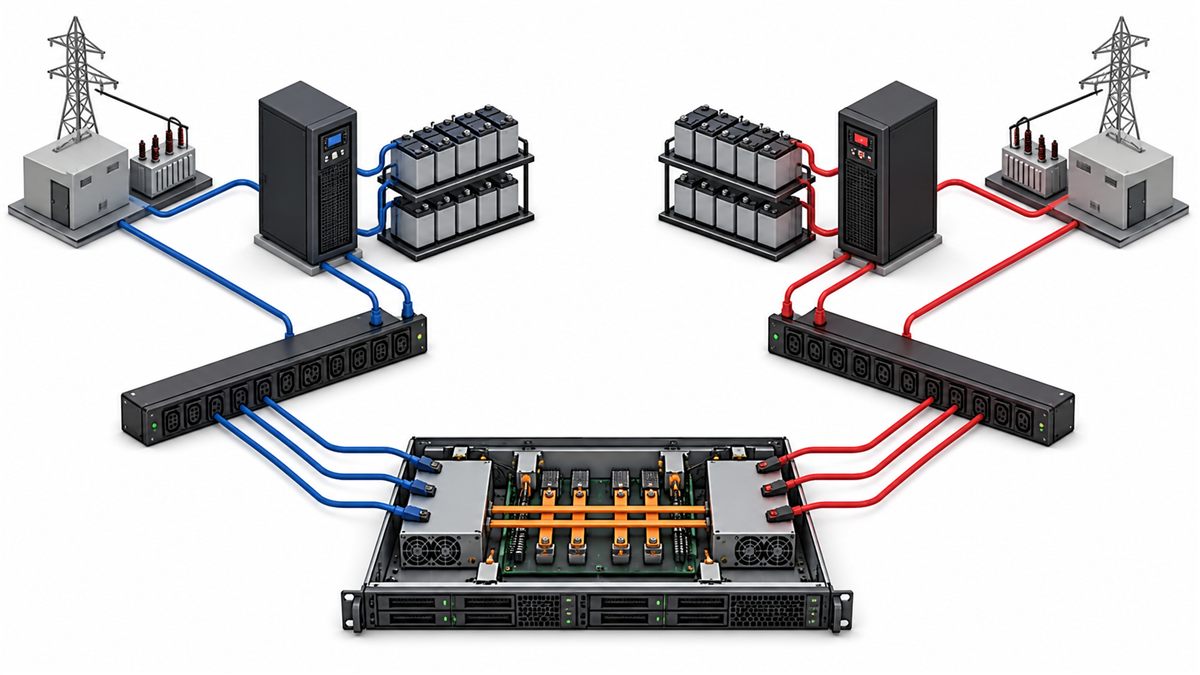
Redundancy begins upstream of the server. A typical A/B design may have separate utility or UPS paths, switchgear, branch circuits, rack PDUs, cords, and PSU modules before joining at the server’s shared DC bus. The actual independence varies by facility. Two rack PDUs can still share a breaker or UPS; two UPS systems can share bypass or maintenance infrastructure. Draw the chain and mark every common component.
If both PSUs plug into the same PDU, the system may tolerate a module failure or cord failure but not loss of that PDU or its upstream branch. That can be an acceptable design when the protected failure set is limited and documented. The error is calling it fully dual-path without identifying the shared dependency. Maintenance procedures should preserve separation so a technician does not accidentally move both cords to one source.
Current sharing affects temperature and available margin
With both modules active, the current-share control aims to divide output. Perfect equality is not required, but imbalance must remain within the supported range. If one unit persistently carries more current, it may operate hotter and closer to its limit. Compare per-module telemetry and confirm sharing at light, typical, and high load, across input and temperature variations.
Some platforms use an efficiency mode that concentrates load on one module while another remains in a standby state. This can move the active unit toward a more efficient operating region, but the mode requires coordinated PSU, PDB, and firmware support. Transition timing and fault response must be validated. It should never be improvised by disabling one module manually.
Output isolation prevents fault propagation
Both modules feed a common bus, so a shorted or unpowered output must not sink destructive current from the healthy source. ORing diodes, ideal-diode controllers, MOSFETs, or other isolation methods may be located in the PSU, PDB, or both. Review reverse-current blocking, short-circuit behavior, device thermal limits, and fault detection. The design should isolate the failing path quickly enough to keep the bus within the server’s tolerance.
Isolation devices also add resistance and heat. Their voltage drop, current rating, cooling, and failure modes belong in the PDB power budget. A design that works with both modules sharing may reveal a connector or ORing hot spot when all current transfers to one path. Thermal testing must include the degraded state.
Transient load can be the limiting condition
Processors, accelerators, storage devices, and fans can change demand faster than management software can react. The surviving PSU must handle credible excursions immediately after the other path is lost. Average power or slow telemetry can miss these events. Use workload measurements and dynamic-load tests to define peak magnitude, slew rate, duration, repetition, and allowed bus deviation.
Firmware power caps can be part of a supported platform strategy, particularly in high-density servers, but their response time and guaranteed behavior must be documented. A power cap that acts after the electrical bus has already collapsed does not replace sufficient instantaneous capacity. Capacity planning should coordinate PSU transient response, PDB capacitance, downstream converter hold-up, and workload controls.
Hot swap is useful only while redundancy remains intact
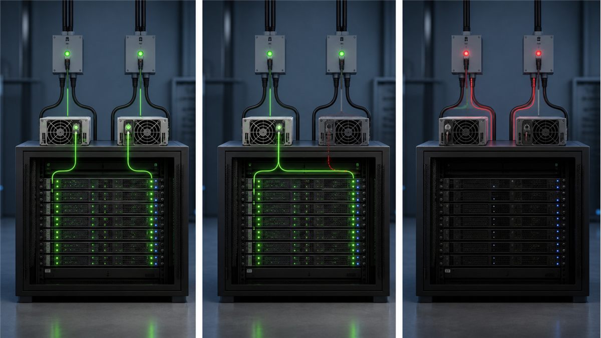
A redundant module is commonly designed for hot replacement, but removability and hot-swap permission are not the same. The module, connector, PDB, and server procedure must support live extraction and insertion. Before removal, verify the correct failed bay, the healthy input path, and sufficient load margin. Removing the healthy module by mistake can shut down the server.
During insertion, staged contacts and inrush control prevent excessive disturbance. The host should recognize the replacement, clear the appropriate alarm, and restore current sharing. Confirm that the replacement is an approved exact model or supported alternative; physical fit and output voltage alone do not establish compatibility.
Management must expose loss of redundancy
A server can continue running after one PSU fails, making a silent degraded state especially dangerous. Local LEDs, BMC alerts, event logs, and remote monitoring should distinguish input loss, PSU fault, removed module, fan fault, and communication failure where the platform supports those states. Alert routing and escalation need testing, not just configuration.
Telemetry can also reveal unequal current, rising temperature, or unstable input before a complete failure. Accuracy and thresholds are model-specific, so compare readings with external instruments during qualification. Avoid using one unverified telemetry number as the only overload protection or capacity signal.
Failure scenarios the design should address
| Event | Expected system response | Key check |
|---|---|---|
| One PSU loses AC input | Healthy path maintains the DC bus | Source independence and survivor capacity |
| One module is removed | Server remains within rail limits | Hot-swap sequence and airflow |
| One PSU output faults | Fault is isolated from common bus | ORing and protection coordination |
| One rack PDU fails | Operation continues only in a true A/B feed design | No unintended upstream common point |
| Management bus fails | Power behavior follows documented safe state | BMC timeout, alarm, and recovery |
This table defines expected behavior without assuming that every platform protects against every event. The system requirement should state which rows are mandatory and what limits are acceptable during each transition.
Thermal behavior changes after a failure
When one supply takes the full load, its internal losses and fan demand rise. The empty or inactive bay can alter pressure and permit hot-air recirculation. Chassis fans may change speed in response to the fault. Measure PSU inlet, exhaust, connector, PDB, and nearby component temperatures during a sustained single-module run at the maximum permitted workload.
Check high inlet temperature and reduced air density at altitude if those conditions are within the deployment scope. Use required blanking panels and keep extraction paths clear. A design should remain safe long enough for the stated repair objective without depending on immediate human response unless that limitation is explicit.
Compatibility applies to the pair as well as the individual module
Mixing PSU models or revisions can create unequal sharing, different fan behavior, firmware alarms, or unsupported management responses. Even modules from the same vendor can have different rails, pinouts, depths, or communication features. Follow the server manufacturer’s supported combinations and qualify any proposed substitution as a pair.
Relevant checks include form factor, blind-mate connector, pin assignment, standby rail, power-good and enable timing, current-share protocol, PMBus identity, airflow direction, output derating, input connector, and hot-swap sequencing. The CRPS redundant power supply integration guide expands on these module-to-PDB details.
A repeatable redundancy validation plan
- Measure or bound server demand across idle, typical, startup, and peak workloads.
- Confirm one module’s usable capacity at deployed input, temperature, altitude, and airflow.
- Run on PSU A alone and PSU B alone at the maximum redundant load.
- Interrupt each AC feed separately and observe the shared bus and management response.
- Remove and insert each module under permitted loads using the approved procedure.
- Apply representative dynamic loads during and immediately after path transitions.
- Inspect current sharing, connector and PDB temperature, fan behavior, and telemetry.
- Verify local indicators, remote alerts, event logs, escalation, and return to redundancy.
Repeat testing after relevant changes to PSU revision, PDB, BMC firmware, chassis airflow, facility input, or workload power limits. Store the validated configuration so procurement cannot substitute a superficially similar module without review.
Operational rules preserve the designed resilience
Label A and B cords and PDUs consistently. Prevent both inputs from being moved to one feed during rack work. Keep compatible spares available and verify their storage and firmware policy. Train technicians to confirm the failed bay and surviving load before extraction. Monitor degraded redundancy as an urgent condition even though the server remains online.
Planned maintenance should test one path at a time and respect facility change control. A redundancy design is only as strong as its operating discipline. Accurate diagrams, asset records, alert routing, and periodic failover exercises keep the original engineering intent intact throughout the server’s life.
Questions about dual redundant server power
Are two PSUs on one PDU still redundant?
They can provide redundancy against certain module or cord failures, but the shared PDU and upstream branch remain common failure points. If PDU or source failure is part of the protected set, use appropriately independent A and B paths.
Can both modules’ wattages be added together?
They may be added for a nonredundant combined-capacity mode only when the platform supports it. For 1+1 operation, the permitted redundant load is limited by one module’s usable capacity under worst supported conditions.
Does hot swap guarantee zero voltage disturbance?
No. The system has specified rail tolerances and transient limits. A supported hot-swap design controls the disturbance so the server remains within those limits. This should be verified under representative load.
How quickly must a failed PSU be replaced?
The service target depends on workload, thermal design, failure policy, and organizational risk tolerance. Because the server has lost redundancy, replacement should be prioritized according to the site’s defined response objective while the survivor remains within its validated limits.