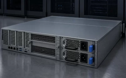
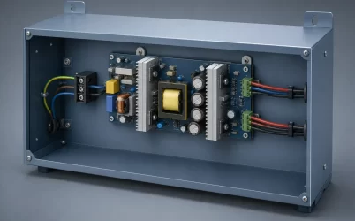
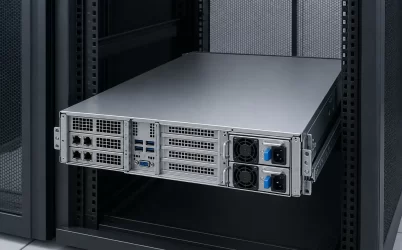
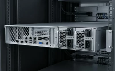
A data center server redundant power supply deployment is commissioned only when each PSU inlet is traced to its intended A/B source, the server is operating in a documented redundancy mode, and the surviving path can support the permitted workload. An authorized loss-of-path check must then produce the expected continuity, alarms, and recovery behavior. Installing two PSUs and two cords is not acceptance by itself.
The commissioning deliverable should state which failures the server is expected to survive, identify where the two paths first share equipment or capacity, and preserve evidence for healthy, degraded, and restored states. This turns an abstract redundancy label into an operational promise that data-center staff can monitor and maintain.
Before assigning outlets, write one continuity statement naming the workload, allowed event, expected behavior, and restoration condition. Example: “The application server must remain online at its approved load after either one PSU module or one assigned rack feed becomes unavailable.”
Topology labels are shorthand, not acceptance evidence:
- 1+1 at the server: one supported module carries the required state; this does not prove upstream-feed independence.
- N+1: N modules carry the defined load and one additional module provides reserve; one feed event may remove more than that margin.
- 2N: two capacity paths exist at a named infrastructure boundary; this does not prove every server connection follows both paths.
Attach the protected boundary to every label. The Uptime Institute Tier Classification System classifies facility infrastructure topology; it does not verify a specific server’s cabling or single-path capability. Commissioning remains open until covered failures, degraded-state signals, and restoration evidence are explicit.
Trace both cords until the paths genuinely diverge
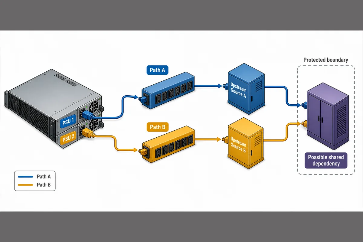
A/B labels on outlets or cable colors are useful operational aids, but they do not prove independence. Build a path schedule that starts at each server inlet and continues through the cord, rack PDU outlet, PDU input, branch distribution, UPS or other protected source, and the documented upstream boundary relevant to the continuity objective.
| Boundary | Path A record | Path B record | Commissioning question |
|---|---|---|---|
| Server connection | PSU bay and inlet identity | PSU bay and inlet identity | Does each inlet belong to the intended supported PSU configuration? |
| Cord | Exact cord asset and destination | Exact cord asset and destination | Can operations distinguish and service one cord without disturbing the other? |
| Rack distribution | PDU and outlet identity | PDU and outlet identity | Are the outlets on the intended separate distribution paths? |
| PDU source | Branch and upstream source | Branch and upstream source | Would the authorized source-loss event remove only the intended path? |
| Shared dependency | First common equipment, capacity pool, control dependency, or facility source | Is that shared point outside the failure boundary promised for this server? | |
The first shared point is not automatically a design defect. It defines where independence ends. Two rack PDUs may be sufficient for a requirement limited to PDU or cord loss even if their paths converge farther upstream. The same layout would not support a claim that the server can survive failure of the shared upstream component.
Common dependencies can also be less visible than the power conductors. Examples include both PDUs supplied by the same branch, two nominal paths assigned to one UPS output, common transfer equipment, shared protection settings, or a management dependency that prevents operators from distinguishing which source failed. Inside the server, the PDB, motherboard, cooling system, and management controller may remain common elements even when the two AC inputs are independent.
Record actual asset identifiers and controlled drawing references in the production schedule. Labels such as “A” and “B” should express the documented topology, not create it.
Make the host policy agree with the rack allocation
The rack can provide independent sources while the server remains unable to support the workload on one source. Conversely, a server may tolerate one PSU-module failure while both cords are connected to the same PDU. Commissioning has to reconcile these two boundaries.
Use the platform documentation and management interface to establish the installed operating mode. Depending on the server, available policies may prioritize redundancy, combined capacity, balanced sharing, or efficiency-oriented operation. Terminology and behavior vary by platform, so the active setting and supported PSU population should be recorded rather than inferred from the number of installed modules.
The required degraded state must fit within the documented capability of the surviving configuration at the deployed input, temperature, airflow, and platform settings. If both modules are needed to carry peak demand, loss of one module is a capacity event rather than a protected 1+1 state. Power caps or workload limits used to preserve continuity should be explicit operational controls, not undocumented assumptions.
For a deeper explanation of how module count, shared components, and upstream feeds create different failure boundaries, see what two server power supplies actually protect. During commissioning, those principles become concrete records: the active mode, the permitted server configuration, the accepted workload state, and the expected response after one specified path disappears.
Input conditions also belong in this reconciliation. A surviving PSU may face a different source condition from its partner, and available output or input current can be conditional on the exact model and platform. The path schedule should therefore reference the applicable input source and host documentation instead of assuming that any energized inlet provides equivalent capacity.
Commission through observable electrical states
A redundancy check should be a controlled sequence, not an unplanned cord pull. The method must follow platform documentation, electrical safety rules, the site method of procedure, workload-owner approval, and the permitted impact scope. Events at a branch circuit, UPS, switchboard, or other shared facility layer should not be initiated merely to prove one server. When a live source-loss test is not authorized, use approved simulation, platform evidence, upstream commissioning records, or documentary verification and state the resulting limitation.
Establish the healthy baseline
Begin with the server in its intended production-equivalent state. Record both PSU identities, input presence, host redundancy policy, workload condition, relevant power readings, rack PDU states, active alarms, and synchronized timestamps. Confirm that no unrelated degradation exists before introducing a test event. A server that begins with an absent module, overloaded path, thermal alert, or stale management data cannot provide clean evidence about the requested failure.
Apply one authorized event at a time
Each test should isolate one failure boundary. A module-removal check examines server-side conversion and hot-swap behavior when the platform expressly supports removal under load. A feed-loss check examines the assigned cord, outlet, rack PDU, and upstream path. Passing one does not prove the other.
| Event | Required preconditions | Expected observations | Abort or escalation conditions | Restoration evidence |
|---|---|---|---|---|
| One PSU module becomes unavailable | Platform-authorized procedure; supported single-survivor capacity; healthy partner | Workload continuity; correct module alarm; surviving PSU remains within supported conditions | Unexpected load interruption, unstable output, thermal excursion, ambiguous module status, or insufficient remaining capacity | Correct module recognized; expected policy active; redundant status restored |
| Rack path A becomes unavailable | Approved site procedure; confirmed A/B schedule; path B healthy | Only the intended inlet loses source; server continues; PDU and BMC events identify the affected boundary | Both inputs disappear, path B becomes unstable, workload exceeds the supported degraded state, or topology differs from the schedule | Path A source returns; both inputs are healthy; event records reconcile |
| Rack path B becomes unavailable | Approved site procedure; confirmed A/B schedule; path A healthy | Only the intended inlet loses source; server continues; alarms name the correct path | Unexpected dependency, ambiguous telemetry, or any condition outside the approved method | Path B source returns and the host reports the intended protected mode |
| Source is restored | Failed path is safe to return; configuration has not changed | PSU input and output recover as designed; management recognizes the module; sharing or policy behavior stabilizes where observable | Repeated transitions, persistent faults, incompatible module state, or failure to regain redundancy | Healthy baseline is reproduced and temporary alarms are resolved according to procedure |
Do not combine a module removal with a feed-loss event unless the continuity objective explicitly includes that concurrent failure and the system has been designed and authorized for it. Ordinary single-fault redundancy commissioning should avoid creating an unprotected second event.
Restore protection, not merely power
Re-energizing an inlet or reinserting a module is not the end of the test. The restored state should show that the exact module is recognized, both intended inputs are available, the configured redundancy policy is active, event logs match the test sequence, and the server has returned to its accepted workload condition. Where current or share telemetry is available, it can help show that the reintroduced module has resumed its expected role; its availability and accuracy remain platform-specific.
Interpret telemetry as three different service states
The monitoring design should distinguish healthy redundancy, supported degradation, and restored protection. A generic “server online” signal cannot do that because the application may continue running while redundancy has already been lost.
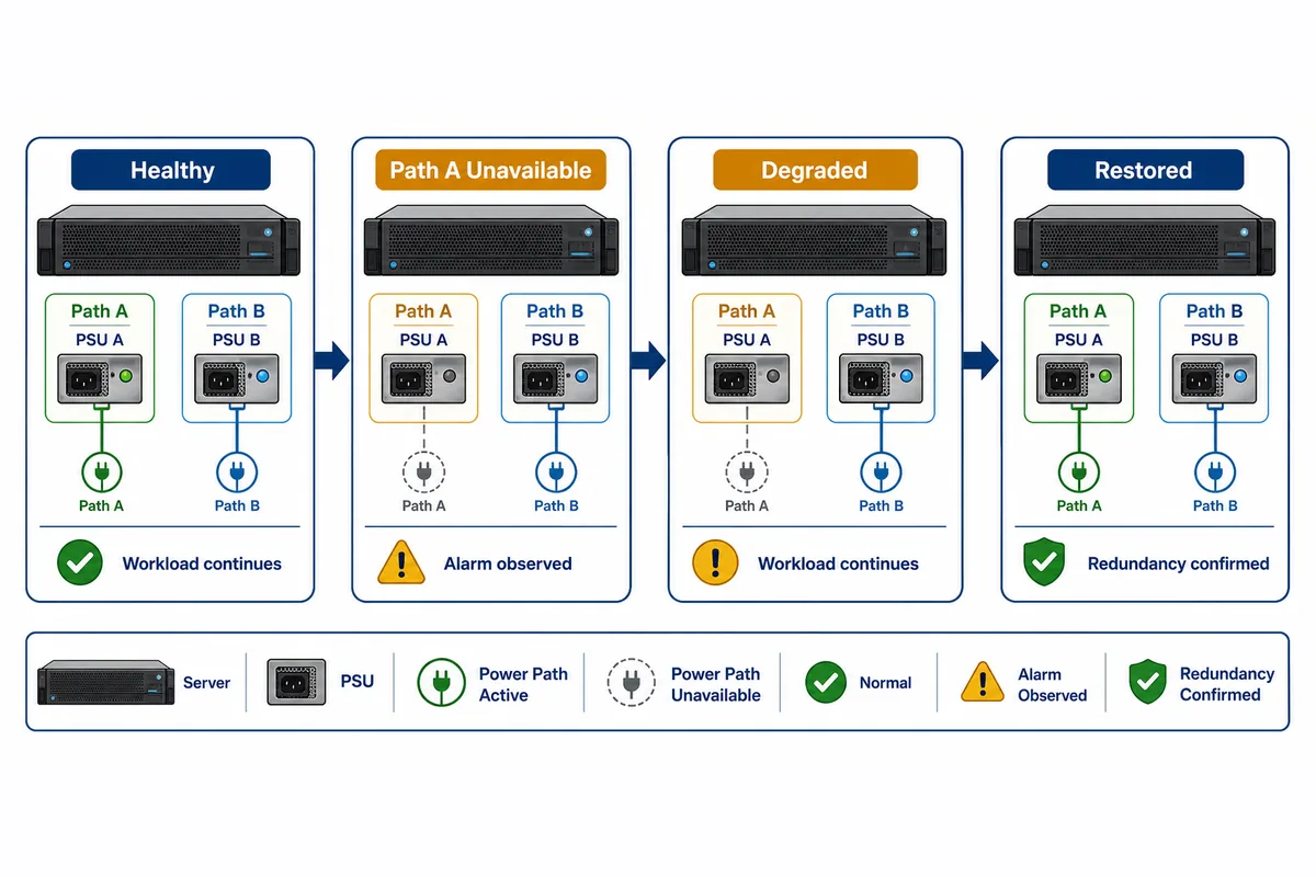
- Healthy and protected: the supported PSU population is present, both intended sources are available, the selected policy is active, and no unresolved power alarm exists.
- Degraded but supported: one defined module or source is unavailable, the server remains within its permitted workload envelope, and monitoring identifies the missing boundary clearly enough for operations to respond.
- Restored and protected: the failed path has returned, the host recognizes the complete supported configuration, and management confirms that redundancy—not merely input voltage—has been re-established.
Useful evidence may come from the BMC event log, PSU presence and input status, platform power readings, rack PDU outlet state, facility alarms, and an application heartbeat. Not every server exposes input current, output current, sharing data, or the same PMBus-derived fields. The commissioning plan should use available documented signals and identify blind spots instead of inventing a universal telemetry set.
Several apparent passes deserve investigation. A server may survive a brief interruption because of energy storage without demonstrating sustained single-path operation. A module-removal test may pass even though both cords terminate on one rack PDU. An application heartbeat may remain healthy while the BMC reports an unsupported PSU pairing. A restored green indicator may coexist with an inactive redundancy policy. The evidence must show that the intended boundary was exercised and that the system returned to the intended protected state.
Keep the handoff record attached to the rack assignment
The final record should be concise enough for operations to use but detailed enough to reproduce the claim. It should include:
- server asset, rack location, installed configuration, PSU identities, and applicable firmware baseline;
- the continuity statement and the exact module, cord, PDU, feed, or upstream events it covers;
- the A/B path schedule, including the first known shared dependency;
- host redundancy settings, workload or power-control assumptions, and applicable input conditions;
- authorized test methods, baseline observations, event timestamps, degraded-state evidence, and restoration evidence;
- events that were not tested, the reason they were excluded, and the documentary evidence used instead;
- record owner, approval date, drawing references, and links to relevant operating procedures.
Broader workload, rack-capacity, source, and cooling data can remain in the existing facility-to-server power requirements matrix. The commissioning record has a narrower purpose: proving that the deployed server and its assigned A/B paths behave as that design expects.
Recommissioning is warranted when a change can alter the continuity claim. Typical triggers include a PSU replacement or revision change, firmware or power-policy update, server relocation, PDU outlet reassignment, cord rerouting, upstream topology modification, significant workload growth, or a new operating condition that changes surviving-path capacity. A repaired cable or cleared alarm does not automatically preserve the original evidence if the path assignment changed.
With this record in hand, operations can answer three questions during an incident: which path was lost, whether the current workload remains inside the supported degraded state, and what evidence will confirm restoration. That is the practical meaning of a commissioned data center server redundant power supply—not two illuminated modules, but a traceable continuity promise from each PSU inlet through its assigned rack path.