A dual output open frame power supply should be selected as two interacting power rails, not as a board with two appealing voltage labels. Define the voltage, current, tolerance, ripple, startup demand, shutdown behavior, and fault response required by each load. Then compare those requirements with the exact model’s individual rail ratings, combined power limit, load conditions, thermal assumptions, and return configuration. The decisive question is whether both outputs remain within specification while the real loads start, operate, change state, and encounter faults together. If the documentation does not answer that question, the behavior remains an item for supplier clarification or bench verification.
Quick answer: specify both loads before filtering products
Begin with a two-rail load-state matrix covering startup, normal operation, peak demand, shutdown, and credible faults. A suitable candidate must support each rail independently and the simultaneous load combination under the intended input, ambient temperature, orientation, airflow, and enclosure conditions. Confirm whether the outputs share a return, require minimum loading, interact through cross-regulation, or respond together when one rail is overloaded. Compare exact part numbers rather than assuming that every member of a dual-output series has the same ratings or behavior.
Define each rail at the load terminals for startup, normal, peak, shutdown, and fault states. Include cable and connector drop, identify overlapping peaks, and note loads that may return energy; nominal component labels are not a sufficient specification.
| Requirement group | Rail A | Rail B | Interaction question |
|---|---|---|---|
| Electrical limits | Voltage, current, tolerance, and ripple by state | Same fields | Which states coincide? |
| Dynamic behavior | Startup, shutdown, peak duration, and fault response | Same fields | Is sequencing or rail continuity required? |
| Connection boundary | Return requirement and terminal drop | Same fields | Are the returns compatible and losses included? |
This is a requirements matrix, not a claim about any model. Complete it before using distributor filters, then compare it with the exact variant documentation.
Read individual rail limits with the combined envelope
A dual-output datasheet can contain several limits that must be true at the same time. Each output may have an individual current rating, while the converter also has a maximum total output power. Certain ratings may apply only with specified airflow, ambient temperature, input voltage, or load distribution. The permitted operating region is the intersection of those conditions—not whichever number is largest.
For a simple initial calculation, determine the simultaneous DC output power:
Total DC output = (Rail A voltage × Rail A current) + (Rail B voltage × Rail B current)
Suppose a hypothetical machine requires 24 V at 1.5 A and 5 V at 1 A during one normal state. The combined load is 41 W. That value does not by itself prove that a nominally higher-powered dual-output supply is suitable. The 24 V rail must support 1.5 A, the 5 V rail must support 1 A, and the exact 41 W combination must fall within any shared loading, cooling, and derating restrictions.
The same calculation should be repeated for every meaningful simultaneous state. Adding both independent peaks can be unnecessarily conservative if sequencing makes them mutually exclusive. Conversely, using only steady-state values can miss an overlapping startup condition. A timeline showing when each load turns on is often more informative than one maximum-current row.
Do not assume unused capacity on one rail can be reassigned to the other. Whether that is possible depends on the converter architecture and the documented limits of the exact variant. A product advertised with a total wattage may still impose a lower ceiling on one output.
Load interaction can decide whether the voltage combination works
Some multi-output converters control one output more directly than another. In such designs, regulation of one rail can be influenced by loading on the other rail. The result may be described in documentation through line regulation, load regulation, cross-regulation, minimum-load conditions, or a recommended load range. The relevant behavior is model-specific.
Cross-regulation matters when the two loads move independently. For example, a logic rail may remain lightly loaded while an actuator rail changes rapidly. If the lightly loaded output rises or falls outside the host equipment’s permitted range during that event, both nominal voltages can be correct while the product remains unsuitable.
Look for explicit answers to these questions in the exact datasheet:
- Does either output require a minimum load to maintain its stated regulation?
- Are regulation specifications stated for independent rail changes or only for a particular loading combination?
- Are ripple and noise limits specified with particular test capacitors, probes, or measurement bandwidth?
- Does the supply define startup order, rise time, overshoot, and behavior under pre-biased loads?
- Does one rail remain present during overload or short-circuit protection on the other?
- Are the continuous ratings different from short-duration peak ratings?
Published output tables must also be read by exact suffix or model number. The official MEAN WELL PD-25 series specification, for example, documents output combinations and electrical conditions by variant. Its role in a comparison is not to establish universal behavior for dual-output supplies; it illustrates why the controlling evidence must follow the exact rail combination being considered.
Return topology and protection behavior affect the host circuit
Two outputs do not necessarily provide two galvanically isolated circuits. Their returns may be internally common, center-referenced, independently floating, or constrained in another documented way. Distributor filters generally cannot resolve this distinction, yet it directly affects grounding, measurement, noise, and whether the rails can be connected in series.
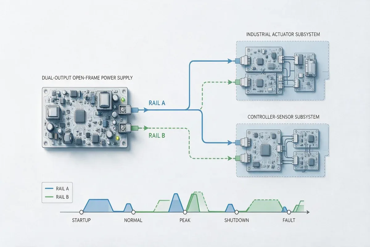
If the host design joins both returns to protective earth or chassis, identify where that bond occurs and whether the power-supply documentation permits it. Multiple return-to-chassis connections can create circulating current or inject switching and load current into sensitive measurement paths. An isolated output can offer flexibility, but isolation should not be inferred merely because a listing displays two voltage values.
Protection must also be evaluated as an interaction between rails. Overvoltage protection, overcurrent protection, short-circuit protection, and overtemperature protection may act on one output, on a shared converter stage, or on the entire supply. Depending on the model, a fault might cause current limiting, hiccup operation, shutdown with automatic recovery, or a latched state. If one rail powers safety monitoring or a controller responsible for recovering the other load, the distinction has system consequences.
“Dual output” states the number of available voltage outputs. It does not prove isolation, independent regulation, independent protection, or continued operation of one rail after the other faults.
Loads that can drive energy back toward the supply require additional attention. Motors, inductive actuators, and externally powered signal interfaces can raise a rail or force reverse current unless the host contains an appropriate path for that energy. Use manufacturer documentation or an agreed application review rather than assuming that a standard output can absorb reverse power.
The open-frame rating belongs inside a real enclosure
An open-frame AC-DC board depends on the host product for mechanical protection, mounting, airflow, wiring, protective earthing, and parts of the final safety and electromagnetic compatibility implementation. Its usable dual-output envelope can therefore change after installation.
Compare the candidate’s documented rating conditions with the proposed enclosure. Natural-convection and forced-air ratings are not interchangeable. Fan location, airflow direction, nearby obstructions, board orientation, altitude, and inlet temperature can influence component temperatures. If a higher rating depends on forced air, the evidence should define where and how airflow is applied rather than merely stating that a fan exists somewhere in the enclosure.
Physical integration also changes electrical performance. Long or undersized conductors create rail-specific voltage drops, while routing high-current switching loads beside low-level sensor wiring can increase noise coupling. Keep AC input wiring, protective-earth connections, output conductors, and signal wiring arranged according to the applicable product documentation and final-equipment requirements.
Clearance around the board is not only an assembly convenience. Conductive chassis parts, fasteners, cable shields, and mounting hardware can affect required insulation distances and airflow. Because approval conditions and installation requirements vary by model and end product, a certification mark on the board should not be treated as automatic approval of the completed equipment.
Compare exact variants through a two-rail evidence matrix
A commercial shortlist becomes useful when every candidate is expressed through the same two-rail fields. Product-family names and distributor filters can locate possibilities, but the comparison should use the exact orderable variant and its controlling documentation.
| Evidence field | Candidate 1 | Candidate 2 | Disposition |
|---|---|---|---|
| Manufacturer, exact model, and revision | Documented value | Documented value | Accept or resolve identity |
| Rail A voltage and current range | Exact variant data | Exact variant data | Compare with every required state |
| Rail B voltage and current range | Exact variant data | Exact variant data | Compare with every required state |
| Combined loading restriction | Limit and conditions | Limit and conditions | Plot required simultaneous states |
| Minimum load or cross-regulation condition | Documented or unresolved | Documented or unresolved | Request evidence or test |
| Startup, sequencing, and hold-up behavior | Documented or unresolved | Documented or unresolved | Match the host state sequence |
| Return and isolation arrangement | Documented topology | Documented topology | Reconcile with grounding plan |
| Rail-to-rail fault response | Documented or unresolved | Documented or unresolved | Define permitted system response |
| Cooling and derating conditions | Applicable curve or instructions | Applicable curve or instructions | Compare with installed environment |
| Mechanical drawing and connector details | Controlled documents | Controlled documents | Confirm mounting and wiring |
| Availability and lifecycle information | Supplier response | Supplier response | Assess production and service risk |
“Not documented” should remain visible rather than being converted into an assumption. A missing cross-regulation limit, fault response, or cooling condition may not disqualify a candidate immediately, but it changes the work required before approval. Supplier clarification, an application note, representative test data, or controlled bench testing may close the gap.
Verify the states that carry purchasing risk
Bench work should focus on unresolved behavior that could change the purchase decision. Measure both rails at the same time while reproducing the intended load states. A single multimeter reading at no load cannot reveal startup interaction, transient deviation, ripple, protection response, or voltage movement caused by the other rail.
A focused plan may include cold startup, warm startup, independent load steps on each output, simultaneous peaks, minimum-load states, input interruption, normal shutdown, and authorized overload or short-circuit checks. Record voltage at the load terminals as well as at the supply when wiring drop matters. Oscilloscope measurements need appropriate probing, grounding, bandwidth, and test setup so the instrument does not create or hide the observed disturbance.
Thermal verification should reproduce the intended board orientation, enclosure, wiring, ambient condition, and airflow path. Monitor the locations and operating limits defined by the manufacturer where available. A board operating in open air on a bench does not reproduce heat recirculation, cable obstruction, or inlet-temperature rise inside the finished equipment.
Destructive or hazardous fault testing is not implied by a general verification plan. Mains-powered open-frame supplies expose hazardous energy and voltages, and tests should be performed only by qualified personnel using suitable protection, isolation practices, instruments, and an approved procedure.
Make the quotation describe the two-rail result
The request for quotation should identify the exact required rail combination, load-state matrix, input range, cooling condition, enclosure assumptions, return topology, connector or lead requirements, approvals relevant to the end product, required documentation, production quantity, and lifecycle expectations. Ask the supplier to identify the exact model and any conditions that prevent it from meeting a listed state.
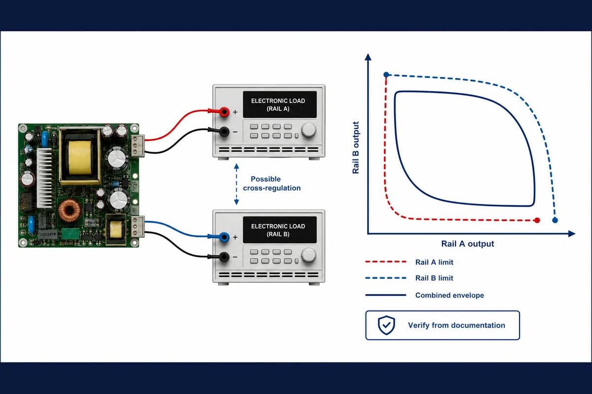
If a standard candidate closes the two-rail requirements, preserve its complete part identity and documentation in the purchase record. If no catalog product supports the required combination, load interaction, connector arrangement, or environmental condition, use a custom open-frame power supply design boundary to distinguish a contained platform modification from a genuinely new converter requirement.
The useful outcome of a dual output open frame power supply search is not simply a board that lists two voltages. It is an exact, orderable variant for which both loads fit inside the individual and combined ratings, their interactions are understood, and the installed enclosure preserves the conditions behind those ratings. That evidence makes price, availability, and supplier comparisons meaningful without turning an unresolved two-rail behavior into a production risk.