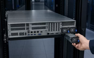
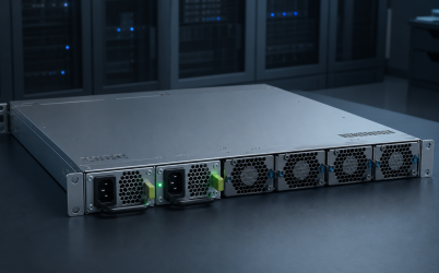
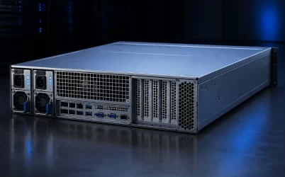
A custom open frame power supply is worthwhile when the host equipment cannot accommodate a standard board without compromising its mechanical layout, electrical behavior, cooling path, or interconnects. “Custom,” however, can mean anything from a connector change on an established platform to a new converter topology. The first engineering task is therefore to define the boundary of change. A narrow, platform-based modification usually contains cost, schedule, and approval risk; a ground-up design gives more freedom but transfers far more verification work into the program.
Customization begins by drawing a boundary around the platform
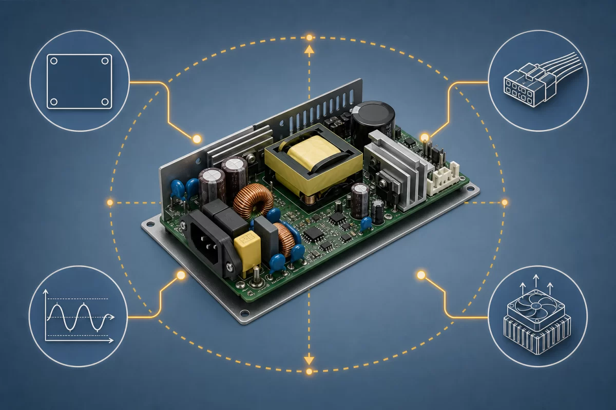
Open-frame supplies are components intended to live inside final equipment, not self-contained boxes. Their exposed PCB makes board outline, component height, mounting, air movement, and cable approach unusually visible to the system designer. That visibility can make customization look simpler than it is. Moving a terminal may appear mechanical, yet the new copper path can change conducted noise, current density, insulation spacing, or the loop area of a fast-switching node.
A productive request separates three levels of work. A configuration selects supported options already designed into a platform, such as an available output setting, connector, fan supply, or signal. A platform modification changes limited mechanical or electrical details while preserving the qualified conversion architecture. A new design changes the power stage, magnetics, control method, isolation system, or operating envelope enough that prior evidence can no longer carry most of the technical argument.
| Project boundary | Typical request | Main trade-off |
|---|---|---|
| Configuration | Existing voltage option, supported connector or harness | Least freedom, strongest reuse of existing evidence |
| Platform modification | Board outline, mounting points, connector position, control signal | Useful fit improvement with targeted re-evaluation |
| New design | Different topology, unusual transient envelope, multiple rails, severe height limit | Maximum design freedom with the broadest development burden |
The host enclosure owns requirements the bare board cannot own
A board can have component-level safety evidence, but the finished machine determines accessibility, fire containment, protective earthing, wiring, pollution exposure, ventilation, and separation from nearby conductive parts. The UL explanation of Recognized Components is explicit that conditions of acceptability govern how a component is used in the end product. That distinction matters in a custom program: a change that remains electrically modest may still conflict with the housing, wiring, or temperature conditions attached to the original evaluation.
The applicable end-product standard also depends on what is being built. IEC describes IEC 62368-1 as a hazard-based safety standard for audio/video and information and communication technology equipment; it is not a universal label for every open-frame application. Industrial measurement equipment, household appliances, and medical equipment can lead to different requirements. The project should identify target markets and the end-product standard before fixing isolation construction, leakage-current targets, protective-earth strategy, or component approvals.
This is why a request such as “make the board 10 mm narrower” is incomplete. The useful input is a three-dimensional keep-out model showing chassis walls, fasteners, vents, conductive shields, user-accessible openings, nearby boards, and cable paths. A mounting hole is not just a coordinate: it can establish a conductive path, create a creepage constraint, or place PCB stress near a heavy magnetic component.
Mechanical freedom competes with thermal and EMC margin
Open-frame power density is inseparable from the installation. Heatsink orientation, component height, vent impedance, fan position, and the temperature of air entering the supply determine how much heat can leave critical semiconductors and magnetics. A datasheet rating under forced air is not automatically available in a quiet enclosure or behind a restrictive filter. One manufacturer’s open-frame installation guidance, for example, directs users to the model specification for required airflow and direction. The general lesson is not to copy its numerical clearances into another design; it is to preserve the exact cooling conditions behind a rating.
Thermal changes also interact with electromagnetic compatibility. Raising switching frequency may reduce some magnetic dimensions but can increase switching loss and move noise into a different spectral region. Rotating a heatsink can improve airflow while increasing capacitive coupling to the enclosure. Extending output leads can improve assembly access while increasing radiated loop area and degrading remote-load regulation during fast current steps. Customization should therefore preserve margins, not merely reproduce a pass/fail result at one operating point.
The most useful thermal description is a map: inlet-air range, airflow direction and minimum condition if forced air is used, neighboring heat sources, orientation, altitude, expected load profile, and allowed component or case temperatures. For EMC, document cable length and routing, shield and earth connections, chassis material, input filtering outside the board, and the intended test configuration. These inputs prevent a supplier from optimizing a board for an imaginary enclosure.
Output behavior is a waveform, not just a voltage and current
Two applications with the same nominal watts can require different converters. A motor, capacitive load, radio transmitter, display backlight, and embedded computer each place a different time-domain demand on the output. The requirement must distinguish continuous load, short-duration peak load, repetition rate, startup energy, and allowable voltage deviation. It should also say how the load behaves when current limiting begins.
Protection behavior deserves similarly precise language. “OCP required” does not reveal whether the host expects constant-current limiting, foldback, hiccup restart, or a latched shutdown, nor whether automatic recovery could cause a machine to cycle indefinitely into a fault. Overvoltage, overtemperature, short-circuit, and input brownout behavior should be connected to the host’s safe state. Auxiliary rails, power-good, remote enable, remote sense, or analog control are valuable only when their logic levels, sequencing, isolation boundary, and failure behavior are defined.
A platform modification is often attractive when nominal output and dynamic behavior already fit and the problem is mainly packaging or interconnection. A new topology becomes more defensible when the load needs an unusual peak-to-average ratio, tight transient recovery within a constrained output capacitance, bidirectional energy flow, multiple tightly sequenced rails, or an input range the platform was not built to handle. These are architecture questions, not connector options.
A useful development process reduces uncertainty in layers
The fastest route is not necessarily the one with the fewest prototype spins. It is the route that resolves the highest-cost unknowns before they propagate into tooling, compliance samples, firmware, and production fixtures.
- Freeze the operating envelope. Define input source and disturbances, continuous and dynamic loads, ambient and cooling conditions, target markets, life expectations, acoustic limits if relevant, and abnormal states.
- Compare the envelope with an existing platform. Record which requirements are already supported, which require a documented option, and which disturb the original architecture or approval evidence.
- Prove the spatial concept. Use the real enclosure model, PCB keep-outs, connector mating space, harness bend radius, fastener access, insulation barriers, and the air path. A fit model can reveal a bad customization boundary before electrical work begins.
- Evaluate coupled risks. Review every requested change for thermal, EMC, safety, control-loop, manufacturability, and service consequences rather than assigning it to a single discipline.
- Build evidence progressively. Early prototypes answer topology and fit questions; later builds should use representative components, enclosure, wiring, airflow, and assembly processes so that pre-compliance evidence resembles the product that will ship.
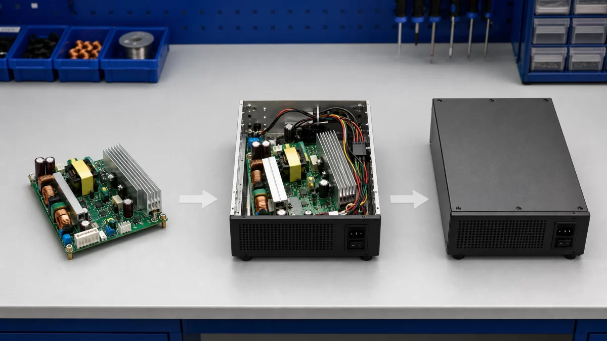
That sequence is deliberately different from a generic end-of-project qualification checklist. Its purpose is to decide how much customization the application actually needs. If the spatial concept fails, there is little value in polishing conducted-emissions results on the wrong board geometry. If the load waveform invalidates the platform, connector negotiations should not hide that fact.
Production constraints should shape the design before the last prototype
A custom board becomes a product only when it can be built consistently. Component availability, approved alternates, transformer construction, thermal-interface placement, creepage-sensitive assembly, adhesive or staking processes, firmware programming, test access, and traceability all affect continuity of supply. A one-off prototype may tolerate hand-routed wires or manually adjusted components that are unsuitable for repeatable production.
Define which parameters require 100 percent production testing and which belong to periodic or design verification. Output voltage and basic functional checks alone may not reveal an incorrect safety-critical component, a reversed fan signal, a compromised earth bond, or poor dynamic response. Conversely, turning every laboratory test into a production test can add cost without improving control. The production plan should follow the failure modes created by the chosen customization, not inherit a generic test list.
Change control is particularly important for open-frame equipment because substitutes can affect spacing, temperature, and noise. The approved bill of materials, PCB revision, magnetics specification, firmware version, test limits, and deviations need a common release record. This is also the point at which expected volume matters: modest volumes usually favor a supported platform modification, while sustained volume and a requirement that cannot be met cleanly may justify dedicated tooling and a new architecture.
The boundary is successful when the enclosure and converter agree
The best custom open frame power supply is not the board with the largest number of special features. It is the least disruptive design that satisfies the host’s real mechanical, electrical, thermal, safety, and production constraints with defensible margin. Start with a supported platform when its conversion behavior already matches the load; modify it where enclosure integration creates measurable value; move to a new design only when the requirement genuinely crosses the platform boundary.
For background on the responsibilities that remain with the host equipment, Powernexu’s open-frame switching power supply integration article covers mounting, spacing, grounding, and enclosure-level EMC. Keeping that general integration territory separate leaves the custom project focused on a harder question: which changes earn their cost and which changes quietly erase the evidence and margin that made the original platform useful.