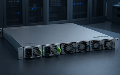
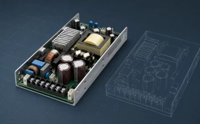
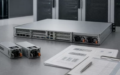
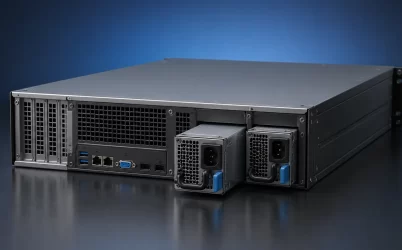
A redundant 2U server power supply must fit and operate as part of a specific chassis assembly; “2U,” “redundant,” and even “CRPS” do not establish compatibility by themselves. Before ordering, identify the PSU cage, module dimensions, insertion direction, blind-mate interface, power distribution board (PDB), output harnesses, airflow direction, control signals, and supported firmware. Then calculate protected capacity from one surviving module under the deployed input and thermal conditions. A candidate is suitable only when its documentation closes all of those boundaries and supports the required failure and replacement behavior.
Quick answer: qualify the complete assembly, not the 2U label
For commercial comparison, validate each candidate module against a controlled assembly comprising the PSU bay or cage, PDB, output connections, signal wiring, airflow, and platform support. A replacement order may contain only the PSU module, but approval should still reference the exact module part number and revision plus the supported host assembly. Use a compatible-platform matrix or approved bill of materials, dimensioned drawings, interface documentation, conditional output ratings, and documented failure and replacement behavior. If the supplier cannot identify those items, use the listing for discovery only—not as deployment evidence.
A 2U requirement leaves several identities unresolved
Two rack units describe the height class of the server chassis, not the dimensions of the removable power module. A 2U server may use narrow common redundant modules, a proprietary hot-plug pair, a larger redundant assembly, or another platform-specific arrangement. Rear-panel space can also be shared with expansion slots, network interfaces, fans, storage access, and management connectors, so two 2U servers may allocate very different envelopes to power.
CRPS can narrow the architectural category, but it still does not prove interchangeability. A CRPS power supply works through a defined mechanical, electrical, control, management, and thermal interface. Specification generation, module length, keying, output contacts, signaling, airflow, and host support can differ. The exact module and platform pairing therefore remains more useful than a generic CRPS description.
| Catalog term | What it establishes | What remains unresolved |
|---|---|---|
| 2U | The rack-server chassis height class | PSU bay dimensions, orientation, extraction space, and mounting |
| Redundant | More than one power path is intended | Topology, surviving capacity, fault isolation, and feed independence |
| 1+1 | One module is intended to back up one required module | Usable output after derating and whether the full configured load is protected |
| Hot-plug or hot-swap | Live replacement is claimed under supported conditions | Compatible PDB, insertion sequence, inrush control, firmware behavior, and service procedure |
| CRPS | A common redundant module architecture is referenced | Exact generation, pin interface, mechanics, firmware, and approved platform list |
Trace the candidate from the rear panel to the motherboard
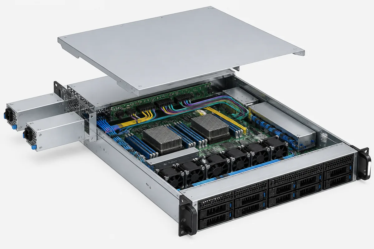
The fastest way to expose incompatibility is to follow the physical and electrical path instead of comparing headline wattage. Begin at the rear-panel opening, continue through the PSU cage and blind-mate connection, then follow the PDB and every downstream branch to the motherboard, processors, accelerators, drives, fans, and peripheral cards.
Mechanical fit includes the service path
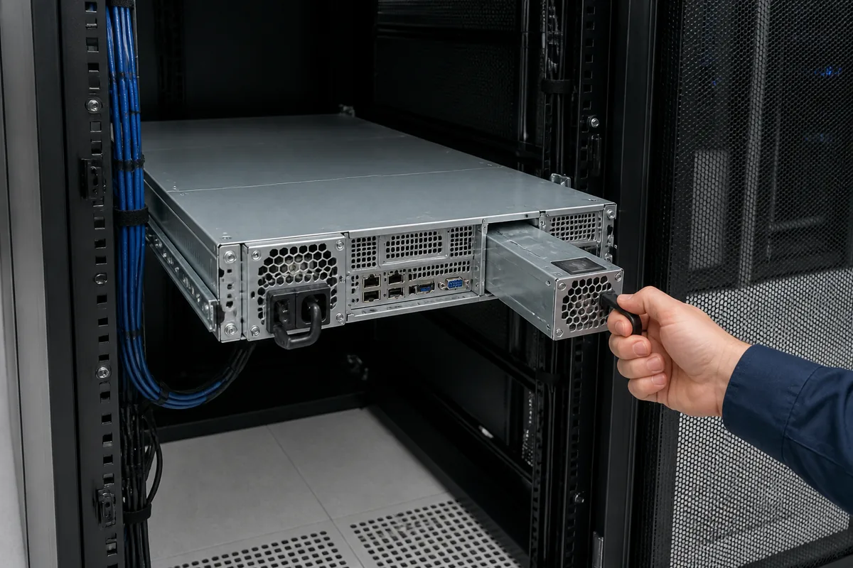
Request a dimensioned module drawing and a chassis drawing showing the complete PSU installation. Width, height, and depth are only the first three checks. The review should also cover latch location, handle travel, guide rails, keying, insertion stop, connector engagement depth, cage tolerances, and the clearance needed to remove a module while the server remains in the rack.
Cable-management arms, rack doors, neighboring power cords, vertical power strips, and wall clearance can obstruct extraction even when the module fits the bay. A field-replaceable supply that requires moving the chassis or disconnecting unrelated cables does not deliver the intended 2U service experience.
The PDB defines the usable electrical route
The blind-mate connector must align mechanically and match electrically. Contact position, main output, standby power, return paths, control and sense signals, communication lines, and sequencing are model-specific unless an applicable specification and revision establish otherwise. An adapter or modified harness may appear to solve connector mismatch while leaving current capacity, signal sequencing, fault isolation, or safety behavior unresolved.
The PDB then has to distribute the surviving module’s output to the actual server branches. Its bus structure, connectors, cable assemblies, and branch limits may impose a lower usable boundary than the PSU label. The CRPS PDB assembly interface is therefore part of the compatibility decision, not an accessory to be selected after the modules.
Validate redundant capacity against one surviving path
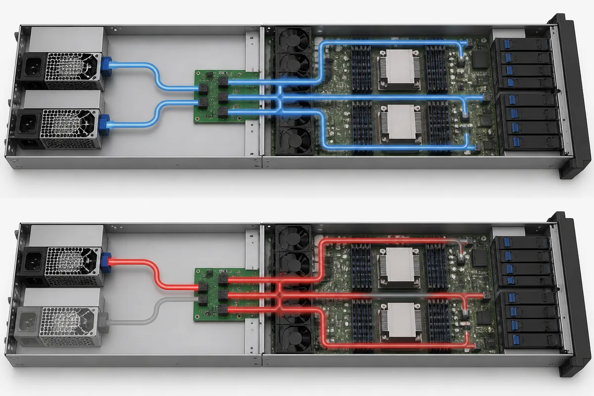
Do not add the ratings of two modules when evaluating a 1+1 assembly. Freeze the permitted server configuration and determine its credible sustained and transient demand, including the operating states allowed by the platform. Then compare that demand with one module’s usable output after applying every condition stated for the exact part number, including input voltage, inlet temperature, airflow, altitude, and any model-specific derating. The approved load must remain within the lowest applicable limit imposed by the surviving module, PDB, bus structure, connectors, cables, and downstream branches. The server power supply wattage methodology provides the deeper load-modeling process.
| Qualification state | What to verify | Required evidence |
|---|---|---|
| Both modules operating | Stable sharing, status reporting, and operation within the supported load envelope | Platform documentation plus measured results under the permitted workload |
| Declared module or input failure | The healthy path carries the load without exceeding module or distribution limits | Recorded output, alarms, temperatures, and server behavior against predefined limits |
| Failed module removed | The shared bus remains supported and the failed path stays isolated | Approved service procedure and platform-level qualification result |
| Replacement inserted and recovered | Insertion does not disrupt the server, and the pair returns to its supported redundant state | Documented sequencing, fault clearance, current sharing, and management status |
Define acceptance limits before testing and run the sequence at the most demanding permitted workload and thermal condition. If independent input feeds are part of the availability requirement, verify the feed topology separately; two modules connected to one upstream source do not protect against loss of that shared source. Approval should apply only to the tested module, PDB, chassis, firmware, and configuration baseline.
Make the supplier evidence match the quoted part number
Product listings can identify manufacturers, formats, and wattage classes, but they are not compatibility records. Supermicro’s power-supply matrix is an example of manufacturer platform information used to match power supplies with supported systems. Treat such a matrix as evidence only for the combinations it actually lists, and pair it with the exact model’s datasheet, drawings, and ordering information.
For every candidate, request evidence tied to the quoted ordering code and revision:
- Dimensioned drawings for the module, cage, and mating location.
- The supported PDB, chassis, motherboard, and firmware combinations.
- Input and output ratings with applicable voltage, temperature, airflow, altitude, and derating conditions.
- The connector definition for power, return, standby, control, sense, and communication contacts as applicable.
- Current-sharing, fault-isolation, degraded-operation, and hot-plug behavior for the proposed assembly.
- Protection and recovery behavior for the exact model.
- Efficiency or regulatory evidence naming the quoted model and applicable operating category.
- Required PMBus, telemetry, alarm, inventory, and BMC support.
- A complete bill of materials identifying whether modules, cage, PDB, harnesses, cords, and mounting hardware are included.
A “typical” datasheet, an undimensioned photograph, or a statement that a module is “standard CRPS” does not close these interfaces. Apply change control to substitutions as well: a different module revision, fan, PDB, connector, or firmware baseline requires review even when the marketing family name remains unchanged.
Use a comparison matrix that exposes disqualifying gaps
A useful procurement matrix does more than rank price and wattage. It shows whether each candidate can be approved, what evidence is missing, and which party owns any unresolved integration work.
| Comparison field | What to record | Reason to reject or hold |
|---|---|---|
| Exact identity | Manufacturer, module part number, revision, PDB, cage, and harness | The supplier quotes only a family name or generic category |
| 2U installation | Bay envelope, orientation, latch, keying, insertion depth, and extraction clearance | No dimensioned assembly drawing or interference remains |
| Electrical interface | Verified mating connector, contact functions, sequencing, and downstream outputs | Pin compatibility is assumed from appearance |
| Protected capacity | One-module usable output under site input and thermal conditions | The configured load exceeds any surviving-path limit |
| Power distribution | PDB, bus, cable, and branch limits for the installed load map | The PSU rating exceeds a downstream interface limit |
| Thermal path | Airflow direction, system impedance, fan coordination, and derating conditions | The chassis airflow conflicts with the module requirement |
| Redundant behavior | Sharing, fault isolation, degraded operation, replacement, and recovery | Redundancy is claimed without system-level evidence |
| Management | Presence, power-good, alerts, telemetry, inventory, and firmware support | The BMC cannot interpret required status or fault information |
| Compliance | Applicable reports, certificates, model identity, and deployment conditions | Evidence applies to another model or incomplete assembly |
| Service supply | Spare part number, approved alternates, lead time, and revision policy | No controlled replacement will be available during the service life |
| Commercial scope | Included hardware, warranty boundary, support owner, price, and delivery | Critical assembly components are excluded or responsibility is unclear |
The 2U geometry creates its own thermal and service traps
A 2U chassis offers more vertical space than a 1U platform, but that space does not automatically benefit the PSU. Expansion cards, storage bays, a fan wall, motherboard heat sinks, and accelerator ducting can divide the internal airflow into zones. A supply located at the edge of the rear panel may experience a different inlet temperature and pressure than the components used to characterize chassis cooling.
Confirm the PSU airflow direction against the server’s actual front-to-rear or other documented airflow scheme. Recirculation near the rear panel, blocked intake perforations, missing air baffles, or excessive cable bundles can reduce cooling. If the module controls its own fan, the host still needs to accommodate its airflow and acoustic behavior; if cooling depends on system fans, the platform must maintain the required flow during fan faults and the one-module operating interval.
Service access deserves equal attention. Both modules should have identifiable cords and status indicators, and an operator should be able to remove the failed unit without disturbing the healthy module. The latch should remain reachable with the rack populated, while cord routing should not cross the extraction path. These details determine whether hot replacement is a practical operation rather than merely a capability listed in a datasheet.
Move from catalog search to an orderable 2U configuration
- Freeze the server configuration. Record the chassis, motherboard, processors, accelerators, memory, drives, adapters, fans, firmware baseline, and allowed future options.
- Define the protected state. State which module, cord, feed, or upstream source may be lost and how long the server must operate before service.
- Identify the assembly interfaces. Obtain drawings and documentation for the bay, cage, PSU, PDB, output harnesses, BMC connection, and rack-side cords.
- Screen capacity under deployed conditions. Compare the permitted server load with one surviving module and every downstream limit after input and thermal conditions are applied.
- Resolve operational behavior. Require documented sharing, fault isolation, alarms, removal, insertion, and recovery behavior for the exact platform.
- Control the quotation. List the requested part numbers, revisions, included items, approved alternates, evidence documents, spares, and responsibility boundaries.
If no candidate closes those six steps, a different power architecture may be safer than forcing a nominally similar module into the chassis. Warning signs include undocumented adapters, insufficient single-module output, conflicting airflow, unavailable PDB documentation, unsupported BMC behavior, or a spare strategy based only on physical resemblance.
The procurement specification should identify the complete compatibility baseline: approved module and revision, mating PDB and cage, required harnesses and cords, supported chassis and firmware, deployed operating limits, qualification evidence, and replacement parts. The quotation should separately state which of those items are included. A replacement order may contain only a PSU module, but it should reference the qualified assembly so that compatibility does not have to be rediscovered after the server is deployed.