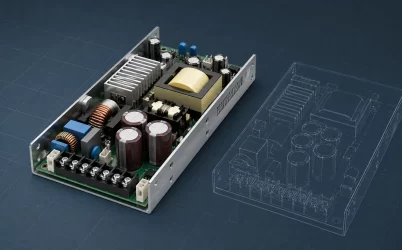
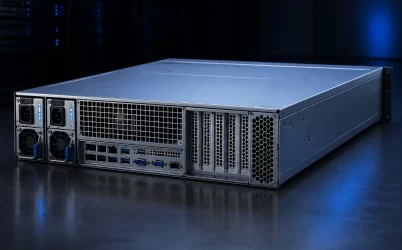
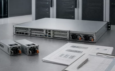
A 1U dual redundant server power supply is a complete chassis architecture, not merely two narrow modules installed side by side. The height limit compresses conversion, airflow, distribution, and service access into the same rear-panel space, while redundancy requires either module to carry the supported server load after the other is lost. A sound integration therefore begins in the failed state: confirm surviving-module electrical capacity, inlet conditions, cooling, PDB current path, and workload behavior before treating two installed PSUs as resilient power.
One rack unit is a shared spatial budget
The server’s nominal 1U height describes the enclosure, not a universal PSU outline. Inside that height, sheet metal, guide rails, connector alignment, extraction hardware, insulation, fan structure, PCB components, and manufacturing tolerances all compete for vertical space. Width and depth then compete with rear I/O, expansion cards, storage backplanes, motherboard components, and the fan wall. A module that is marketed for 1U equipment can still be mechanically incompatible with a particular cage or power distribution board.
Start with a section view through the installed system. It should show the module envelope, insertion axis, blind-mate connector, guide and latch features, inlet and exhaust openings, cable or busbar transition, and clearance to the lid and motherboard. The removal path matters too: rails, rack posts, cable-management arms, and adjacent cords must leave enough rear access to release and withdraw one module without disturbing the other.
The current Open Compute Project M-CRPS specification illustrates why a common family still needs configuration control: mechanical envelope, power signal connector, management behavior, airflow, and rated operating conditions form a system contract. It should not be interpreted as proof that every server labeled CRPS or 1U accepts every module in that broad family.
Airflow has to cross the converter before it can remove the heat
A slim module achieves power density partly by using a small, fast airflow path. Pressure drop across its inlet grille, internal components, heatsinks, transformer, and exhaust grille determines how much air reaches the hot parts. The chassis may supply cool air from the front fan wall, the PSU may contain its own fan, or both may contribute. Those arrangements are not interchangeable because fans in series and parallel respond differently to system impedance.
Recirculation is especially costly in 1U. A rear obstruction, missing air baffle, open PSU bay, or poor seal between fan zones can send heated exhaust back toward an inlet. Cable bundles and tall components can starve one side of the chassis even when aggregate fan airflow appears adequate. Evaluate temperature at each module’s inlet rather than assuming the data-center cold-aisle temperature reaches the converter unchanged.
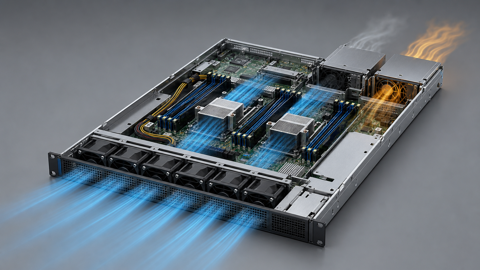
The single-module state changes the thermal problem. Electrical loss is concentrated in the survivor, and its fan behavior may rise accordingly, while the failed or removed module can alter backpressure and leakage. A dummy or blanking strategy may be needed for an empty bay, depending on the chassis design. If the server depends on airflow through both modules, loss of one fan can be a thermal event even when the remaining converter has sufficient electrical rating.
The useful power number belongs to the surviving module
In a typical 1+1 arrangement, two modules can share load during normal operation, but their nameplate ratings are not added to claim redundant usable output. The supported redundant load is constrained by what one module can deliver under the actual input voltage, inlet temperature, altitude, airflow, and manufacturer-defined derating. If a system needs both modules to meet peak demand, it may still have two power sources, but it does not have full module redundancy at that demand.
Consider a hypothetical server whose sustained workload reaches 1,100 W at the DC bus and whose selected modules are each rated for 1,200 W only under the intended installation conditions. Nominally, one module has 100 W of steady-state margin. That arithmetic does not establish suitability. The survivor must also tolerate workload excursions, transition dynamics when its partner disconnects, distribution losses, auxiliary loads, fan behavior, and any applicable derating. The example’s purpose is to expose how little margin remains, not to prescribe a universal percentage.
Commercial server specifications increasingly state this condition directly. For example, the current Supermicro AS-1127H7-N datasheet describes dual redundant power while qualifying full redundancy by configuration and application load. That is the right reading discipline for any 1U server: “dual installed” describes hardware count; “fully redundant” describes supported behavior at a defined load.
The PDB determines whether the second module is truly independent
Both modules usually connect through a cage or midplane to a PDB that combines their outputs and distributes power to the motherboard and other load zones. The board needs controlled ORing or equivalent isolation so a shorted or unpowered source does not pull down the common bus. Current-sharing control must prevent one healthy module from becoming unintentionally overloaded during normal operation. Connector contacts, copper planes, busbars, fuses, hot-swap devices, and branch connectors must all carry the failed-state current with acceptable temperature rise and voltage drop.

There are two different redundancy boundaries to preserve. Module redundancy protects against one PSU failure. Feed redundancy protects against loss of upstream AC or DC infrastructure. Plugging both modules into the same PDU, circuit, UPS, or maintenance domain can preserve the first boundary while leaving the second as a common point of failure. Where independent feeds are required, the modules and server must support the intended input arrangement, and operational documentation should identify which cord maps to which module.
The PDB also defines compatibility. Output voltage alone does not establish a match: the blind-mate connector, pin assignments, precharge and enable sequencing, standby rail, current-share bus, presence detection, power-good behavior, management address, and mechanical keying can differ. Replacing a module by wattage and outline risks damaging equipment or creating a pair that powers the server but does not share, report, or fail over correctly.
A module loss is an electrical and control transition
Before a failure, two active modules may share the bus. When one output disappears or is isolated, the survivor’s current changes quickly, not after an orderly maintenance interval. The control loops in the module and on the PDB, bus capacitance, connector impedance, and the downstream voltage regulators collectively determine whether the DC bus remains inside the host’s acceptable transient envelope. A steady-state capacity comparison cannot predict that transition by itself.
The management path should make the event diagnosable. Depending on the supported platform, the BMC may receive presence, input, output, temperature, fan, warning, and fault information through PMBus or a vendor-specific implementation. The PMBus specification library defines protocol material, but the exact command set and interpretation remain platform- and module-dependent. Procurement should therefore request the supported telemetry and fault mapping rather than assuming every PMBus-capable unit exposes identical data.
Firmware policy can protect redundancy before a failure occurs. Power capping, workload scheduling, fan control, or an alert threshold may keep the supported peak below single-module capacity. Those controls are useful only if the host’s response is fast enough for the event being managed. A BMC cannot compensate for a sub-millisecond bus collapse by issuing a later software command; electrical energy storage and control response must bridge the immediate transition.
Power density shifts constraints into the rack and room
High-density 1U systems can place substantial load behind a small rear area. Cord bend radius, connector temperature, PDU outlet allocation, and service access become physical constraints. Higher input voltage can reduce AC input current for a given power level, subject to the actual module’s supported range and rating, but it does not remove module losses or the need to verify facility compatibility. Efficiency certification also does not establish chassis airflow, redundancy, or host compatibility.
At fleet scale, normal load-sharing mode affects both energy and failure response. Running two modules lightly loaded may place them at a different efficiency point than running one active module at higher load with another in a standby policy. The appropriate mode depends on vendor support, load profile, transition requirements, and the desired redundancy behavior. It should be chosen from the module’s documented efficiency and control behavior, not from a generic assumption that either balanced sharing or cold redundancy is always superior.
Acoustics follow the same physics. A narrow, high-impedance path often needs high fan speed, particularly at elevated inlet temperature or after module loss. A quieter replacement module may change cooling behavior, firmware compatibility, or the supported operating envelope. In 1U infrastructure, fan sound is often evidence of the pressure and heat problem being solved rather than an isolated PSU characteristic.
The failed-state map is the integration deliverable
A useful 1U power drawing should show more than two rectangles marked PSU A and PSU B. It should trace independent input feeds where applicable, the module cage and blind-mate interface, source isolation, current-sharing connection, common bus, branch protection, load zones, airflow direction, monitoring path, and extraction clearance. Beside that drawing, record the supported server load and environmental conditions with either module unavailable.
This map gives the keyword its distinct engineering meaning. A general rackmount server power supply discussion owns chassis fit and service space across rack formats; a general dual hot-plug article owns live replacement. The 1U dual redundant problem is where height, airflow resistance, concentrated power density, and surviving-module capacity collide. If those four constraints are resolved in the same failed-state model, the pair is an integrated redundant power system rather than simply two PSUs occupying one rack unit.