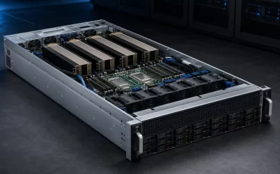
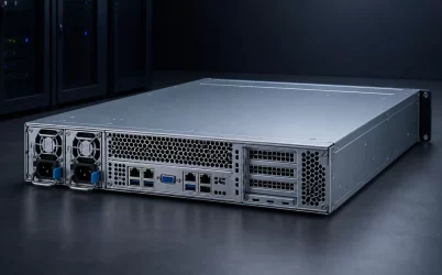
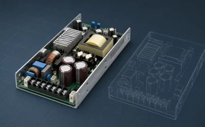
A 495W hot-swap redundant server PSU is a platform-specific service part, not a generic 495-watt block. The replacement must match the server’s supported PSU family, mechanical keying, card-edge interface, firmware expectations, input type, and output rating. Hot-swap then allows a failed module to be removed while its healthy partner carries the server, provided the remaining module can support the live load. This is the central purchasing distinction: the 495W rating describes capacity, while the host platform defines compatibility and the redundant pair creates the safe service window.
The service request starts with the host, not the wattage
Search results for this phrase are dominated by replacement parts for particular Dell PowerEdge generations. That reflects how these supplies are actually bought: an operator has a server, a fault indication, and a narrow maintenance window. Dell’s PowerEdge T420 documentation, for example, lists 495W, 750W, and 1100W redundant AC options but requires two installed supplies to be of the same type and maximum output power. That official restriction is more useful than a marketplace listing that merely repeats “495W hot swap.” See the PowerEdge T420 owner’s manual.
Begin with the server model, generation, chassis configuration, and installed PSU part identity. Record both the customer-facing part number and any manufacturer or regulatory identifiers visible on the label. A number that differs by one suffix can represent a revision, regional input cord arrangement, efficiency option, or a part intended for another platform. The server vendor’s parts list, service manual, or support matrix should arbitrate the match.
This territory differs from a capacity analysis of a 495W dual-hot-plug redundant server power supply. Capacity asks whether one module can carry the workload after a loss. Fleet replacement asks whether the candidate module belongs in the bay at all and whether inserting it preserves the supported redundant configuration.
A matching shell can still hide an incompatible module
Two supplies may share a similar handle, grille, and enclosure yet differ where the server makes contact. The card-edge location, contact pattern, insertion depth, latch position, guide rails, and stop features determine whether the module seats correctly. Electrical identity adds the main output, standby supply, presence detection, power-good signaling, remote sense, current-share connection, and management bus behavior. These details are commonly implemented at the module-to-PDB interface and are not established by outside dimensions.
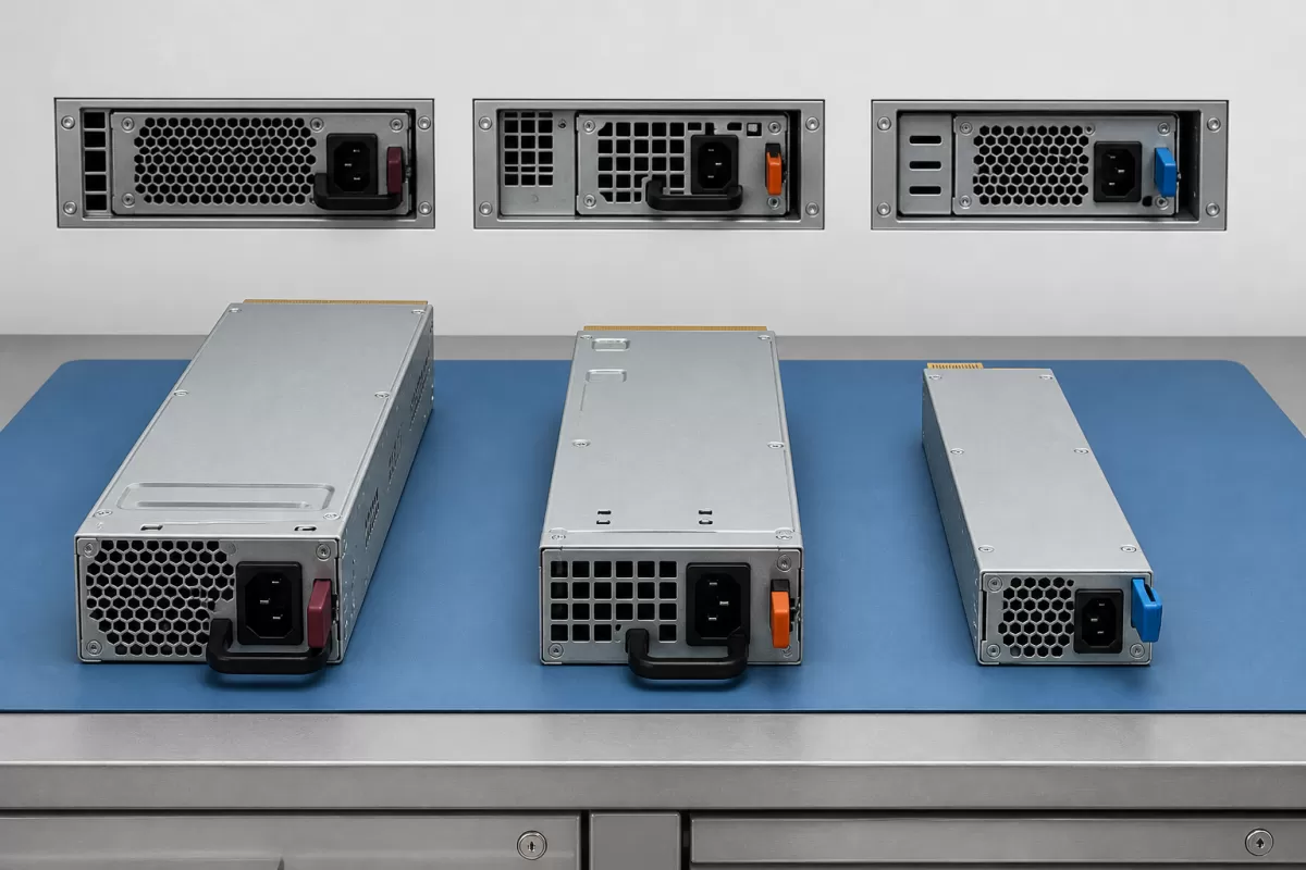
Firmware and management behavior can create a further boundary. A module may energize but still generate a mismatch warning, suppress redundancy, report incomplete telemetry, or run under a less favorable control policy. Treat “it powers on” as an observation, not proof of an approved spare. The meaningful outcome is that the BMC identifies both supplies normally, their health states are clear, and the vendor-supported redundancy mode remains active.
| Identity layer | Evidence to compare | Risk if ignored |
|---|---|---|
| Platform | Server model, generation, chassis option, vendor support list | Unsupported module or disabled redundancy |
| Mechanical | Envelope, guides, latch, insertion depth, connector location | Incomplete seating or damaged mating hardware |
| Electrical | Input type, outputs, standby rail, interface and rating | No start, overload, or incorrect system behavior |
| Control | Current-share, presence, power-good, management compatibility | Warnings, uneven sharing, or missing telemetry |
| Operational | Airflow direction, efficiency option, approved pairing rules | Thermal conflict or an unsupported mixed pair |
Hot-swap is a controlled change of electrical state
During normal redundant operation, both modules may share load according to the platform’s policy. Removing one module causes the surviving supply to assume the required output while isolation circuitry prevents the departing branch from pulling down the common bus. Connector sequencing and module controls help ensure that low-energy signal contacts and high-current contacts change state in the intended order. On insertion, inrush control limits the disturbance caused by charging the incoming module’s internal capacitance before it joins the shared output.
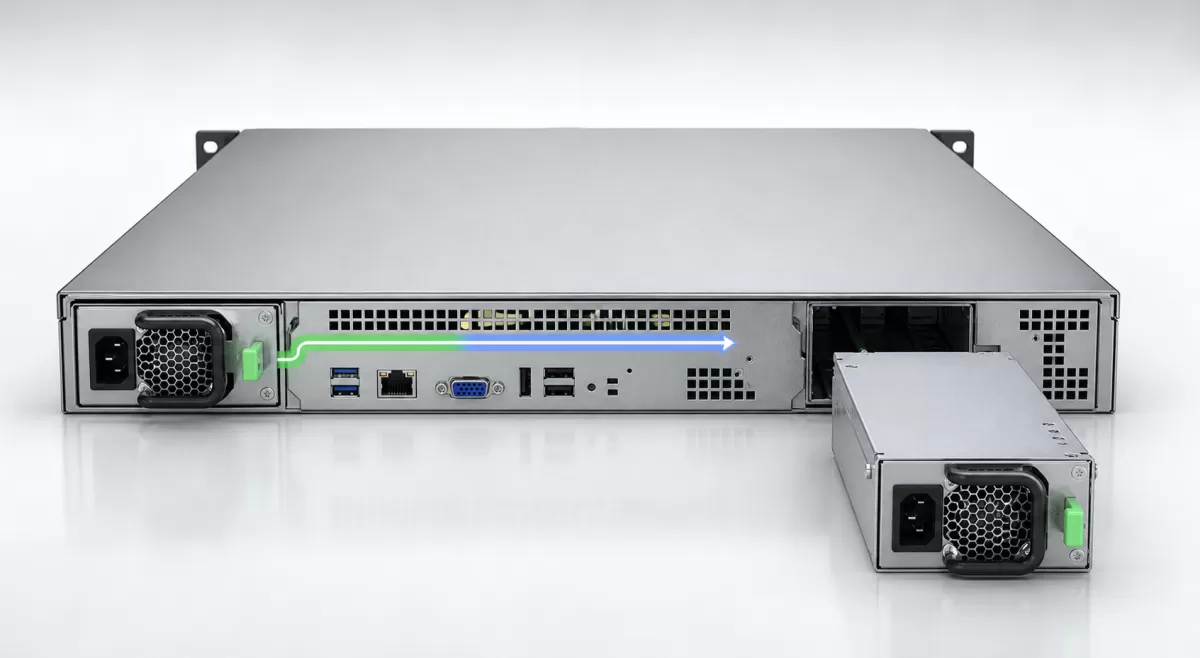
That sequence does not make every removal safe. The server must already be in a supported redundant state, and the remaining PSU must have capacity at the actual input voltage and operating conditions. A failed, unplugged, or mismatched partner leaves no redundancy. Likewise, removing the healthy module after confusing the bay indicators can turn a serviceable warning into an outage.
Power cords define another part of the event. In an A/B-fed installation, identify which cord and upstream PDU feed each PSU before touching the hardware. Disconnect the cord from the module being removed, release its latch, and withdraw it straight along the guides. Never use resistance as a reason to force insertion; a mechanical conflict is evidence that the spare or its orientation needs to be checked.
A disciplined replacement takes less time than recovering from a wrong one
- Confirm the failed side. Correlate the PSU LED with the BMC event and bay identifier. Check that the other module reports healthy and that the server remains in its intended redundancy mode.
- Read the live load. Use the platform’s available power telemetry or supported sizing tool. If one 495W module cannot support the present configuration under the documented conditions, reduce load or schedule a shutdown rather than assuming hot-swap implies unlimited continuity.
- Match the spare. Compare supported part identity, output rating, input type, efficiency option where pairing rules require it, connector and latch geometry, and airflow direction. Follow the platform manual when it requires identical modules.
- Preserve the healthy path. Trace the cord for the failed bay before unplugging anything. In dual-feed racks, avoid disturbing the healthy feed, PDU outlet, or cable retention.
- Exchange one module. Remove only the identified unit, inspect the bay for obstruction or damage, then insert the replacement evenly until its latch seats. Attach the correct input cord after the module is mechanically secure unless the vendor procedure specifies a different sequence.
- Watch the transition. Allow time for initialization. Confirm normal LEDs, BMC identification, input presence, output contribution, and restored redundancy. Retain the event record and spare identity with the maintenance ticket.
This is a service workflow, not a universal procedure for every server. Vendor instructions take precedence because latch operation, indicator meanings, cord sequence, and initialization time can differ by platform.
Fleet spares should be compatibility groups, not 495W bins
A shelf labeled “495W PSU” encourages the wrong substitution. A stronger inventory record groups spares by the set of hosts that officially accept them. Each group can include platform generations, supported part and substitute numbers, input type, efficiency designation, firmware constraints, airflow direction, and the number of deployed servers. The physical bin should mirror that record so a technician cannot easily select a look-alike from another family.
Commonality is valuable when it is documented. It can reduce the number of spare types and increase the probability that a replacement is available at the affected rack. But commonality should never be inferred from wattage or enclosure appearance. HPE’s current Modular Common Redundant Power Supply QuickSpecs illustrate both sides of this principle: the design is common across specified supported platforms, while the same document states that the new form factor is not compatible with earlier server generations. The official HPE QuickSpecs therefore define a supported pool rather than a universal module.
For refurbished hardware, preserve provenance. Record whether a spare is new, vendor-refurbished, or third-party refurbished; capture its actual part labels; and keep warranty and supplier information. Do not erase a host restriction merely because a secondary seller lists several models in one title. A cross-reference is useful only when it is backed by the server manufacturer or another accountable technical source.
Mixed modules can create a false sense of restored redundancy
The most deceptive outcome is a replacement that fits, starts, and leaves the server running but does not restore the expected pair. A BMC warning may indicate unequal ratings, different technologies, or unsupported mixing. Current sharing could be restricted, a power-capping policy could change, or redundancy could remain degraded. The technician should close the ticket only after checking the system state, not merely after seeing a green light on the new module.
Also distinguish a PSU fault from an upstream or common-path fault. If both modules report input loss, investigate the PDU, cords, branch circuit, or transfer path. If replacements repeatedly fault in the same bay, the mating connector, PDB, sensing circuit, or airflow path may be implicated. Repeatedly swapping modules can consume good spares without correcting the failed boundary.
A 495W class can be appropriate for modest enterprise, storage, or edge servers, but no workload label proves fit. Installed processors, drives, memory, add-in cards, fan demand, ambient conditions, and platform derating determine the surviving-module requirement. Powernexu’s broader hot-swap server power supply overview explains the live insertion mechanism; the immediate replacement task remains narrower: identify the supported module, protect the known-good power path, and verify that the host reports a complete redundant pair after the exchange.
The useful spare is the one the server can recognize and support
For a 495W hot-swap redundant server PSU, serviceability comes from three facts aligning at once: one healthy module can carry the current server state, the replacement is approved for that exact host and pairing policy, and the live insertion completes without disturbing the shared bus. A wattage match solves only one of those facts. Build fleet records around platform evidence, keep spares separated by compatibility family, and make restored redundancy—not successful insertion—the end of the maintenance event.