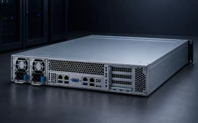
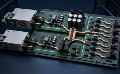
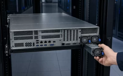
A 2U GPU server redundant power supply must sustain accelerator load movement and the complete host after a module or input-path failure, inside a chassis only 3.5 inches high. The useful design question is not a generic wattage total: it is whether the PSU pair, PDB, cables or busbars, GPU connector zones, fans, and upstream feeds can carry the worst permitted combination of steady demand and transient behavior in every required operating state. A platform-approved PSU configuration is the starting point because 2U GPU layouts vary widely in accelerator count, distribution voltage, cooling, and redundancy policy.
Begin at the GPU connectors and trace power backward
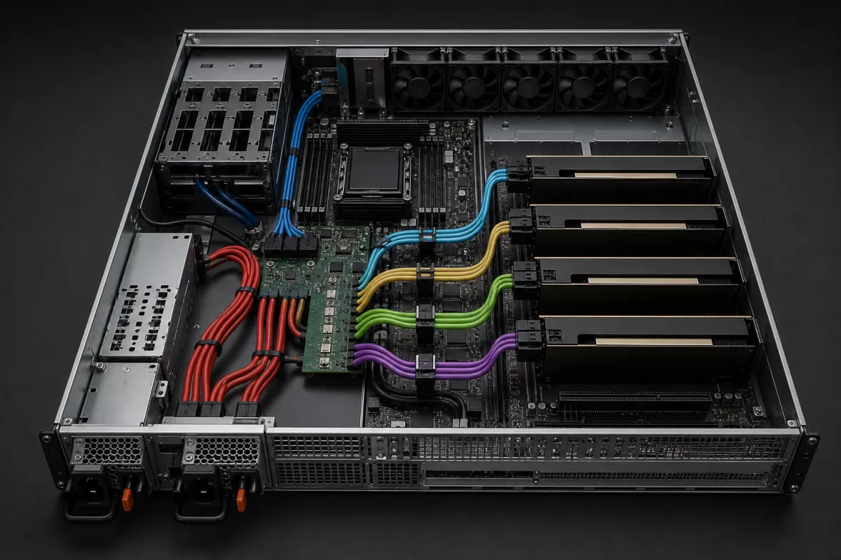
The accelerator cards are the load endpoints, but their current does not arrive directly from the AC inlet. Power moves through the PSU outputs, blind-mate or cable interfaces, a distribution board, copper planes or harnesses, and card-specific connectors. CPU voltage regulators, memory, storage backplanes, network adapters, and the fan wall draw from the same architecture. Each branch has a current limit and a thermal environment, so an acceptable total can still overload one local path.
This is the territory that separates the article from the broader GPU server power-supply sizing overview and the mechanical 2U server PSU layout analysis. Here the central problem is their intersection: high-dynamic accelerator branches share a short, congested 2U distribution and cooling path while redundancy changes which conductors and converters carry the load.
A source-to-load map should identify the rating basis for every branch, not merely draw lines. Document the supported input range, PSU output bus, PDB limits, connector family and contact allocation, harness gauge and length where applicable, and the platform-approved accelerator combinations. Do not transfer a pinout, cable, or module between servers on visual similarity. The OCP Platform Infrastructure Connectivity specification illustrates why distribution paths are explicit engineering objects: it describes balancing current across paired PICPWR connections to avoid overloading one path. That requirement is implementation-specific, but the interpretation applies broadly—parallel copper does not share safely by assumption.
A GPU transient travels through every conversion stage
GPU demand can change faster than facility meters or slow BMC polling reveal. Local capacitors and downstream regulators initially support a step, then the PDB and PSU control loops respond, followed by the upstream source. The voltage deviation at an accelerator is therefore the combined response of multiple impedances and control systems. A module with adequate continuous output may still be unsuitable if the supported host cannot keep its rails inside permitted limits during the workload’s power steps.
NVIDIA’s official DCGM Pulse Test documentation states that the diagnostic produces rapid GPU power and current changes intended to expose platform power-delivery instability. It also makes an important boundary clear: a successful selected workload is not comprehensive PSU certification. For engineering use, that means a pulse-oriented workload is one piece of evidence. It should be combined with the server vendor’s supported configuration, rail measurements at meaningful points, event logs, and the actual application behavior.
Time scale matters. A facility reading averaged over seconds can support energy and capacity planning while missing a millisecond-scale droop. BMC telemetry helps correlate GPU activity, PSU input/output readings, and faults, but its sampling rate may not capture the peak. Oscilloscope measurements require appropriate probes, bandwidth, grounding, trigger conditions, and safe access; they should be performed by qualified personnel under the platform’s procedures. The objective is not to chase an arbitrary spike value, but to determine whether the installed power path remains within documented limits.
The failed state rearranges both electrical and thermal load
In a conventional 1+1 pair, losing one module does not halve the server workload. The survivor must support the entire permitted host load at the actual input voltage and environment. If the platform uses more than two modules or another N+1 scheme, surviving capacity must be derived from that approved topology rather than from the phrase “redundant PSU.” Installed ratings cannot simply be added and called redundant output.
The transition itself is significant. Current that had been shared moves to fewer converters and distribution paths. The survivor’s internal loss and fan demand can increase. If a failed module is removed, the open bay may alter rear pressure or recirculation unless the chassis design or service procedure manages it. Meanwhile, GPU workload controls may continue to request high performance until firmware detects a power event and applies a cap or power-brake response, if the particular platform supports such behavior.
The OCP M-CRPS specification offers a useful standards example by defining failover behavior and output-voltage expectations under stated 1+1 test conditions. It should not be treated as proof for an unrelated server. Its engineering lesson is that redundancy is an observed transition at a bus with specified capacitance, load, and timing—not a static count of PSU handles.
2U packaging turns airflow into a shared power constraint
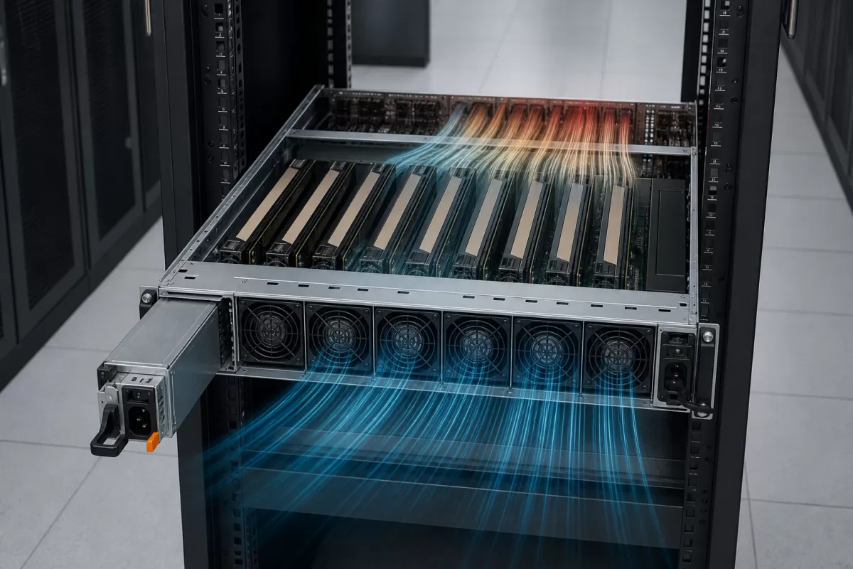
Two rack units provide more vertical room than 1U, yet full-length accelerators, risers, memory, drives, and large connector bundles compete for the same cross-section. A GPU card can obstruct flow to another card; a cable bundle can disturb the fan outlet; rear PSU exhaust can interact with accelerator exhaust. The fan wall consumes electrical power precisely to preserve component temperatures, so cooling demand belongs in the failure-state power budget.
Air-cooled 2U GPU servers often rely on high-pressure, high-speed fans and carefully sealed ducts. A small mechanical change—different accelerator thickness, an unsupported blanking arrangement, misplaced cable, or absent PSU—can bypass the intended path. Liquid-cooled accelerators reduce some air-side heat but do not remove power and airflow needs from memory, voltage regulators, networking, drives, PSUs, and coolant-distribution hardware. The server vendor’s supported thermal configuration remains authoritative.
Input voltage can also alter the usable operating envelope of a high-power PSU. For example, Supermicro’s official SYS-220GQ-TNAR+ product page lists different available output for its installed PSU at different AC ranges. That is evidence for that model, not a universal GPU-server curve. The practical interpretation is to record the exact facility range and cord/PDU path before assuming the nameplate maximum is available in both normal and failed states.
Distribution voltage changes current, not the workload
Many servers distribute a 12V main bus; newer high-density architectures may use 48V or 54V farther into the system and convert nearer the loads. For the same transferred power, the higher-voltage path carries less current, reducing the current-squared component of conductor loss when resistance and other conditions are comparable. It also introduces different converters, connectors, control behavior, and safety considerations. Neither architecture is universally interchangeable or preferable outside a supported platform.
The choice determines where heat and transient energy storage sit. A 12V PDB may deliver very high current across short copper paths. A higher-voltage architecture moves part of the conversion closer to GPU or motherboard zones, which can ease central distribution current while concentrating DC-DC thermal design near the loads. In 2U, those zones are already crowded. Procurement therefore needs the complete voltage architecture, not a request for a PSU wattage detached from its PDB.
Branch symmetry deserves attention even when all accelerators are identical. Harness length, connector contact resistance, board-plane geometry, and airflow can make nominally parallel positions behave differently. Temperature and voltage data should be correlated by physical slot and branch. Swapping workload placement or cards during diagnosis can help distinguish an accelerator issue from a distribution-zone issue, provided the platform and software support the test.
Telemetry should reconstruct an event, not just report health
A green PSU status value after a server reset does not explain the preceding milliseconds. Useful evidence aligns accelerator activity, PSU warnings, input-feed events, PDB or BMC logs, rail behavior, fan response, and any power-cap action on one timeline. PMBus can provide standardized power-management commands and data structures; the official PMBus specification archive is the primary reference. Exact command support, update rate, accuracy, and fault latching remain module- and platform-specific.
Event reconstruction also exposes common failure-domain mistakes. Two PSUs connected to one PDU may survive a module fault but not loss of that PDU. Two independent feeds can still converge at a shared PDB. A branch connector can overheat without either PSU reaching its total limit. A fan fault can cause throttling before the electrical ceiling is reached. “Redundant” describes selected protected paths, not immunity from every common component.
Power-capping policy belongs on that same timeline. A cap may protect a known infrastructure boundary, but its effect depends on how quickly the platform applies it, which devices it governs, and what happens if management communication is delayed. A configured cap is not a substitute for hardware protection or surviving PSU capacity. Treat it as a coordinated operating control whose supported behavior must be obtained from the server and accelerator documentation.
The architecture is complete when the worst transition has a path
A credible 2U GPU power design can trace each accelerator branch back to a supported source, state what changes after the largest required fault, and explain how heat leaves the chassis during that interval. It reserves surviving capacity at the real input condition; keeps local connectors and copper within their documented limits; and uses workload-relevant transient evidence rather than slow averages alone. If any step depends on an unverified cable, PSU substitution, firmware response, or airflow assumption, that step—not the summed wattage—is the unresolved power-supply requirement.