A GPU server power supply must support more than the server’s average wattage. It has to carry the sustained CPU, GPU, memory, storage, and fan load while remaining stable during rapid accelerator load changes. In a redundant system, the decisive rating is the power available after one PSU or one AC feed is lost—not the sum of all installed nameplates. The correct choice therefore depends on the measured load profile, transient response, input voltage, redundancy target, distribution losses, airflow, connector and PDB limits, and management compatibility.
Quick Answer
Select a GPU server PSU by calculating the maximum sustained DC load, adding realistic platform growth and transient margin, and then checking that the remaining modules can carry that load after the intended failure. Verify the entire path: AC source, PSU, blind-mate interface, PDB or busbar, cables, connectors, and GPU input stages. A high wattage label alone does not confirm compatibility. For high-density systems, also compare a conventional 12 V architecture with 48 V or 54 V distribution, because current, copper loss, conversion location, and serviceability change with the architecture.
Why GPU Loads Change PSU Selection
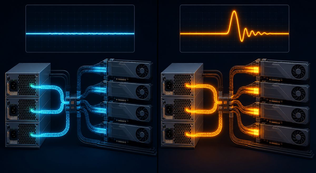
General-purpose servers can also produce fast load steps, but accelerator systems combine several large, synchronized loads. GPU kernels may move from a relatively light state to high utilization quickly, while CPUs, memory, pumps or fans, and storage remain active. The resulting step reaches the power distribution board before facility-level monitoring shows a meaningful change.
A PSU must respond without allowing its output to leave the limits accepted by downstream converters. The design variables include the magnitude and slew rate of the step, control-loop response, output capacitance, distribution impedance, protection timing, and the behavior of paralleled modules. A unit that operates comfortably at a steady load can still cause resets if the system-level transient has not been qualified.
Size the Redundant Capacity, Not the Installed Total
Consider a hypothetical server with a measured maximum sustained DC load of 3,200 W. The integrator reserves 15% for configuration growth and operating variation:
3,200 W × 1.15 = 3,680 W required sustained capacity.
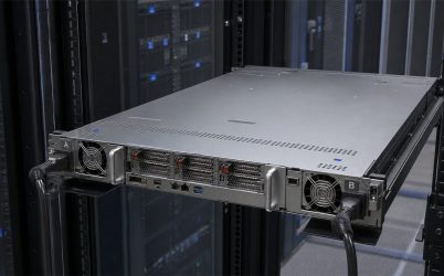
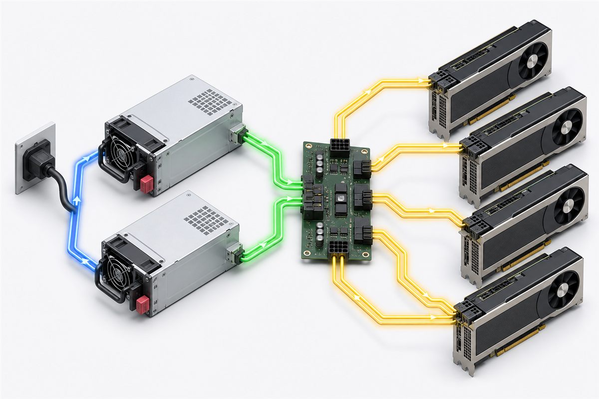
If the design uses 2+1 redundancy, two modules must support 3,680 W after one module is unavailable. Each module therefore needs at least 1,840 W of usable output under the actual input and thermal conditions. Three 2,000 W modules provide 6,000 W of installed nameplate capacity, but the failure-state capacity is 4,000 W. That leaves 320 W above the calculated sustained requirement; transient qualification still has to prove that the platform remains stable.
The same calculation must be repeated after derating. A PSU may have different usable output at low AC input, high inlet temperature, or reduced airflow. The PDU branch, receptacle, cord, and connector current must also support the failure state, because the surviving path carries more current when a module or feed is lost.
Choose Between 12 V and 48 V or 54 V Distribution
Many conventional servers distribute approximately 12 V from redundant PSUs to the motherboard and accelerator power stages. This keeps the architecture familiar and can simplify integration with an existing chassis. Its limitation is current: delivering 4,000 W at 12 V corresponds to about 333 A before downstream losses. High current increases copper area, connector demand, and resistive loss.
At 48 V, the same 4,000 W corresponds to about 83 A. The lower distribution current can reduce busbar and cable loss, but the server then needs suitable intermediate conversion close to the loads. A 48 V or 54 V design is not automatically better for every chassis; it changes safety, protection, hot-swap, converter, and validation requirements. The choice should be made at platform level rather than by replacing one PSU in isolation.
Validate the Complete Electrical and Mechanical Path
| Item to verify | Why it matters | Selection consequence |
|---|---|---|
| Input voltage and branch capacity | Available output and input current can vary with the AC range | Use the rating valid at the deployed input, not an ideal condition |
| Redundancy mode | 1+1, 2+1, and N+N produce different failure-state capacity | Size surviving modules for the full required load |
| PDB, busbar, and connectors | They carry the combined current and can become thermal bottlenecks | Check continuous current, transient current, temperature rise, and mating life |
| Airflow direction and impedance | Dense GPU chassis restrict airflow and raise inlet or exhaust temperature | Validate the PSU in the real chassis and fan-control state |
| Telemetry and controls | BMC policies depend on reliable current, power, temperature, and fault data | Confirm supported PMBus commands, addressing, firmware, and fault behavior |
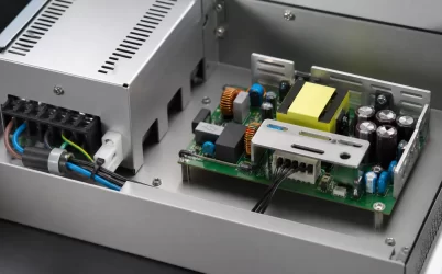
Mechanical fit is equally important. Module dimensions, latch location, rear connector engagement, keep-out zones, and airflow openings must match the cage and distribution board. Do not infer electrical interchangeability from a similar-looking enclosure.
Efficiency and Thermal Design Are Coupled
Efficiency determines both facility input power and heat released inside the rack. For a hypothetical 3,200 W DC load, a 94% efficient conversion point requires about 3,404 W from the AC source and creates about 204 W of PSU loss. At 90%, the same load requires about 3,556 W and creates about 356 W of loss. The difference—roughly 152 W—must be removed by airflow and facility cooling.
Do not select from peak efficiency alone. Compare efficiency across the expected operating range and redundancy policy. Two lightly loaded active modules may operate at a different point from three modules sharing load. Cold-redundancy strategies can improve some operating conditions, but transfer behavior and readiness must be supported and validated by the whole platform.
Qualification Checklist for GPU Platforms
- Measure sustained and transient load at representative accelerator workloads.
- Test loss of each PSU and each upstream AC feed at maximum qualified load.
- Record output deviation, recovery, current sharing, fault isolation, and BMC events.
- Verify hot insertion and removal without resets, connector damage, or unsafe inrush.
- Repeat thermal tests at the worst qualified inlet temperature and airflow state.
- Confirm protection coordination so PSU, PDB, and downstream converters do not trip unpredictably.
- Validate cables, busbars, connector temperature rise, and touch-safe service procedures.
For a related platform-level discussion, see AI server power supply design for GPU load peaks. The final PSU decision should remain tied to the exact chassis, PDB, input source, firmware, and accelerator configuration being qualified.