A server that will not start has not yet identified its power supply as the failed part. To test a server power supply, first establish whether power reaches each inlet, then compare the server’s documented PSU indicators and management events with its actual behavior. On a redundant host, distinguish a missing input feed from a failed module and from a downstream chassis fault. Only a qualified technician with the exact module documentation and suitable equipment should proceed to electrical bench tests. Do not open a PSU enclosure or probe an unknown live connector.
A dark PSU LED, a “PSU failed” event, and power loss under load describe different boundaries. None alone proves the converter is defective. Isolate the failed path without creating an electrical hazard or replacing a healthy unit.
Define what “test” can safely mean at the server
There are three practical levels of server-PSU testing. An operator can inspect accessible indicators, cords, rack power distribution, and the server’s management log without opening equipment. A technician following the host manufacturer’s service method can compare approved modules or move a suspect module between supported bays where the procedure permits it. Electrical characterization on a bench is a different activity: it needs the module’s documented interface, a safe mating fixture, a controlled source and load, instruments, and qualified personnel. A green indicator at level one does not replace the tests at level three; a bench result at level three does not prove a module works in a different server.
Before touching a redundant assembly, identify the host model, PSU part numbers, current workload, the other module’s health, and whether the manufacturer actually supports hot replacement in this configuration. A single-cord, fixed, or cabled PSU can look serviceable from the rear but may require a complete shutdown. If one supply is already carrying a high load, removing the other can consume the remaining capacity margin or trigger host power limiting. Follow the exact server manual rather than inferring a procedure from the presence of two handles.
Visual damage at an inlet, a loose plug, or a displaced latch can guide the next step, but cannot verify regulation or fault isolation. Never short unknown signal pins to “make the PSU start”; standby, enable, share, and sense contacts have platform-specific assignments. A generic internet pinout is not test equipment.
Find where the power path first goes dark
Trace the path in the direction power normally travels: building source, UPS or transfer equipment if present, rack PDU, branch outlet, cord, PSU inlet, module output, PDB, and finally the host. The first missing indication narrows the search. If a PDU outlet has no power, exchanging PSU modules will not restore it. If the rack feed is healthy but a cord is damaged or partially seated, the same module may work once the input connection is restored according to the site procedure. If the PSU appears healthy but the host does not start, the fault may lie beyond the module.
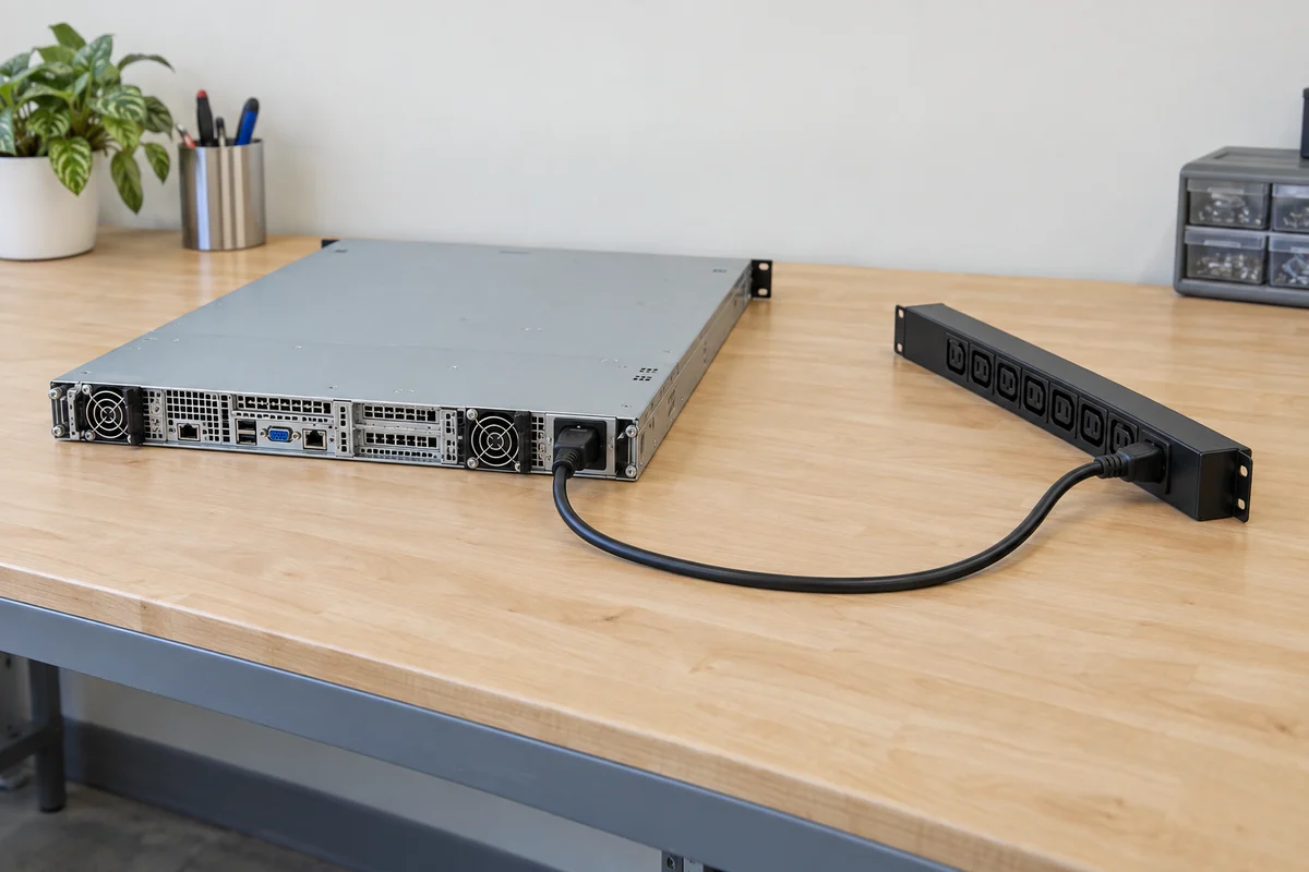
Record whether the symptom affects one cord, both cords, neighboring servers, or a rack. A single-bay warning suggests a narrower path than simultaneous loss on several machines. Two modules plugged into one PDU share an upstream failure domain.
Rack-PDU status is useful, but a live outlet does not prove the cord, module, or PDB is healthy. Zero indicated current can mean standby, a configured idle reserve, disconnection, or failure. Interpret the meter with the host power policy.
Where input voltage must be checked, use the rack or facility-approved method and qualified electrical staff; do not place a general-purpose meter into a live server connector. The acceptable input range is model-specific, and some supplies deliver different maximum output at different mains conditions. A voltage reading at an empty outlet also does not prove the path remains adequate when the server draws current. In a data center, the safer initial tests are usually the PDU’s own diagnostics, cord status, and the host’s management view.
Read the indicator and event log together
Server PSU indicator colors are not a universal code. They can distinguish input present, output active, standby, warning, and failure, but the meaning of a steady or flashing light depends on the host and module family. Some platforms deliberately keep a redundant module in a low-output state. Treat an unlit or flashing indicator as a prompt to consult the exact service guide, not a verdict. If the server exposes a BMC or other management controller, compare the front-panel health light, per-PSU status, input events, system power policy, and timestamped log.
Ask what happened first. A PSU warning that follows a rack-PDU input loss points upstream. An input-restored event followed by normal output can differ from a persistent internal PSU fault. Repeated output warnings under peak workload may suggest a capacity or cooling condition rather than a permanently dead converter. A module that disappears from management while its AC indicator remains normal raises questions about the connector, PDB, management bus, or firmware. The log is evidence about an event sequence, not a direct oscilloscope trace of the DC bus.
Dell’s PowerEdge PSU troubleshooting guidance illustrates the distinction between a redundant hot-plug unit and a cabled nonredundant one, and directs users to the appropriate status and service steps for their system. Its indicator and diagnostic-button details belong to the supported Dell generations; another manufacturer’s lights or management fields can have different meanings. The transferable lesson is to identify the exact assembly before acting.
Capture event time, module bay, input source, and workload before clearing a warning. If the BMC is unavailable, absent telemetry does not prove both PSUs failed; the management network can fail while conversion remains healthy.
Use redundancy to separate one module from the shared chassis
A healthy 1+1 system can offer an unusually useful comparison: two approved modules, two bay positions, two input cords, and one shared server. Yet a controlled comparison must respect load and service limits. Confirm that the remaining module can support the present server state at its actual input voltage and inlet temperature. Check that the host explicitly permits the proposed isolation or replacement procedure. If not, schedule a shutdown. Never pull a live module simply to see whether the machine survives.
Begin with observations that do not change hardware. Do the two bays report different input or output states? Does the warning follow one PDU outlet or cord? Is one module listed as absent despite being physically latched? Are both inputs from a common failed rack source? A management page may call a PSU “inactive” because of a supported cold-redundancy mode, not because the module is broken. Compare the status against the operating mode and current demand.
Where the manufacturer approves a swap test and a known-good spare of the correct part and revision is available, a service technician can use the documented sequence to see whether the symptom follows the module or stays with the bay. A fault that follows one module increases the evidence for a PSU problem. A fault fixed by neither compatible module shifts attention to the bay connector, PDB, chassis wiring, controller, or input assignment. That reasoning is stronger than replacing both supplies because a server failed to boot.
“Follows the module” is not perfect proof: an unapproved spare or intermittent connector can distort the comparison. Preserve the before-and-after events. If the server loses power or the survivor reports overload, stop; repeated swaps will not establish protected capacity.
Different symptoms call for different observations
A server with no signs of life needs an input-to-standby investigation: confirm rack power and cords, then follow the host’s documented power-button, health-light, management, and PSU-indicator guidance. A server that starts but shuts down during boot may have an insufficient or derated PSU, a current-limit event, fan or temperature trouble, or a downstream component fault. A server that remains online after one PSU alarm may have lost redundancy without losing service. These are not interchangeable “PSU tests.”
Intermittent problems deserve particular care. An alarm during a facility transfer, a loose inlet connection under vibration, a fan ramp at high ambient temperature, or a workload power excursion can leave the converter looking normal when examined later at idle. Compare timestamps across the BMC, rack PDU, UPS, and workload monitoring before declaring the incident resolved. Sampling intervals may differ; use the order and scope of events rather than forcing every timestamp into an exact millisecond narrative.
A useful distinction is whether the server lost AC input, DC output, or only a management signal. An AC interruption should have a corresponding upstream context if monitoring was available. A DC bus disturbance with both AC feeds stable points deeper into the server power subsystem or load. A telemetry fault with stable operation can reflect the management path. The observations do not identify a circuit component by themselves, but they prevent a “replace the PSU” response to every alert.
A spare that powers on at light load has not demonstrated stability at the server’s required load, current sharing, or survival after its partner disappears. Return the diagnosis to the state that produced the symptom, within the manufacturer’s permitted procedure.
What a controlled bench test can establish
A qualified laboratory may test a removed module when the exact electrical interface is documented and an approved mating fixture is available. The setup can supply the specified AC or DC input, provide a suitable output load, and measure input, output, and thermal behavior without exposing personnel to uncontrolled conductors. Its purpose should be explicit: perhaps confirming that a returned module starts under a defined load, reproducing an output fault, or distinguishing a module problem from a host integration problem. It is not a casual extension of a rack-side LED check.
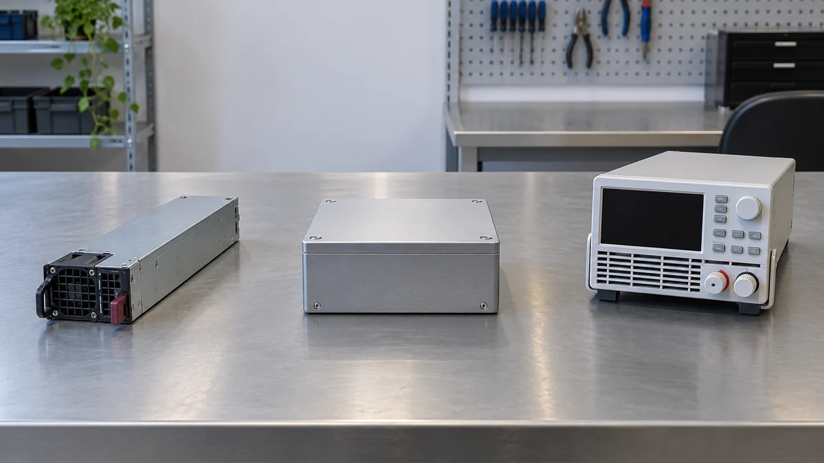
Even the simplest bench result has conditions. Output voltage should be interpreted at a stated load and measurement point; a no-load reading can miss collapse under current. Standby and main outputs may start in a documented sequence, and control pins may require specific host behavior. Ripple and fast excursions require appropriate instruments, bandwidth, probes, and grounding. A handheld multimeter cannot show every short bus dip or transient. An electronic load can reproduce controlled demand, but only if the fixture and module ratings allow it.
Do not open the PSU enclosure. Stored energy and mains-referenced circuitry can remain hazardous after the input is disconnected, and opening the unit may defeat protective barriers or invalidate service controls. Do not improvise an adapter from a connector that merely looks compatible. For many proprietary hot-plug modules, an OEM-approved replacement in the original server is a safer and more informative test than attempting to reverse-engineer a standalone start sequence. When the manufacturer offers a diagnostic procedure, use that specific procedure instead of a universal jump-wire recipe.
Bench success omits the server’s PDB, connector pressure, airflow, firmware, sharing policy, and workload excursions. A module that passes a controlled load yet alarms in one bay points toward host interaction; failure under documented fixture conditions strengthens the case for replacement. Neither result certifies the entire server.
A failed module is not the only diagnostic outcome
The practical endpoint is a fault location with a confidence level. No power at the outlet calls for a facility-path response. A failure that follows one approved module supports replacement; the same failure with both modules in one bay points to the shared assembly. Failure only under workload needs load, input, thermal, and chassis evidence.
Distinguish observations from manufacturer-authorized configuration changes, and note conditions not reproduced. Restore redundant feeds, modules, and alarms to their approved state. A replacement is complete when the server recognizes the module and restores the intended redundancy mode; a lit front panel alone does not establish that result.
If ambiguity remains, escalate with the host identity, module and bay, event sequence, source status, and controlled comparisons. Do not substitute repeated live-removal or improvised pin tests for evidence.