An open-frame power supply for a security system is the AC-to-DC component inside a protected controller, recorder, or equipment cabinet—not a complete security power system by itself. The right output voltage and wattage depend on the actual loads and their wiring. A door controller, an electric strike, a camera, and a network switch may demand different voltages, behave differently at startup, and need different responses when utility power fails. The useful design question is therefore which devices this board will actually feed, what happens at each branch, and which functions must survive an outage.
One enclosure can contain several very different loads
A compact access-control panel may contain a processor board, card reader interface, relay outputs, network electronics, sounder, and a lock circuit. The controller tends to draw comparatively steady power. A lock or strike changes state abruptly and may be mounted many meters away. A recorder adds storage drives whose startup and operating demand differ. A camera may draw through a dedicated DC cable, through Power over Ethernet, or from another source altogether. Adding every nameplate wattage into one number hides these differences.
First identify the supply’s actual DC consumers. A 12 V board inside an access-control enclosure might feed the controller and one or more local 12 V devices, while a separate 24 V circuit powers a lock. A network camera connected to a PoE switch is not necessarily a 12 V branch of that board; its energy reaches the camera through the switch’s power-sourcing equipment. Conversely, a switch installed in the same cabinet may itself need a suitable DC supply. The energy path, rather than the physical proximity of the devices, defines the load budget.
Actuators and electronics should not share an unexplained voltage drop
The most revealing moment in a door panel is often the instant an actuator switches. A solenoid, magnetic lock, or motorized mechanism can change current much faster than the controller’s average load. Current through a long wire and its terminals creates a voltage drop at the device. Shared conductors can also pull down the local voltage seen by sensitive electronics. A controller that resets when a door unlocks may have an adequate nominal PSU rating but an unsuitable distribution path, overloaded branch, transient, or poorly coordinated return.
For a simple resistive estimate, a round-trip conductor resistance of 0.4 ohm carrying 2 A produces a 0.8 V drop. That is an illustrative wiring calculation, not a predicted value for any particular lock or cable. Contact resistance, cable temperature, startup behavior, and return routing may change the result. If the controller and actuator share that conductor segment, both see part of the event; moving the actuator onto a separate protected branch can remove the shared drop even though total supply wattage has not changed.
Switching an inductive load creates another issue. The voltage generated as its magnetic field collapses can disturb adjacent electronics unless the suppression method suits that actuator and its control scheme. Manufacturer instructions for the exact lock and controller should determine suppressor type and placement; a generic diode fitted without regard to release behavior or required response time is not a universal remedy.
Branch protection matters too. If a cable to one door shorts, the desired result is usually an isolated branch fault rather than a collapse of the entire cabinet’s DC bus. Whether that is achievable depends on the distribution module, protective devices, cable gauge, supply current-limit behavior, and the other loads. An open-frame board may include output protection, but that is not the same as independently protected field circuits. The cabinet designer must establish where each branch begins and what a fault on it can disable.
Camera and PoE loads need their own accounting
“Security system” often brings cameras to mind, but camera power is easy to count at the wrong point. If a camera receives PoE, the switch or injector is the electrical load presented to the upstream supply. The camera’s stated power class or maximum consumption helps size the PoE port and the switch’s aggregate PoE budget; it is not itself a direct output specification for an unrelated 12 V open-frame board. Switching and conversion losses inside the network equipment also separate power at the source from power delivered to the camera.
Some network equipment uses a higher-voltage DC input, while its internal circuitry manages PoE negotiation and port delivery. A 54 V open-frame supply may be a candidate DC source for compatible equipment, but matching “54 V” on two pages does not prove that the switch accepts the supply’s full operating range, output tolerance, connector arrangement, startup behavior, or maximum current. The PoE standard applies to the power-sourcing equipment and powered-device interface; an upstream AC-DC board does not become a PoE-certified PSE merely because its DC rail is near the voltage used in some PoE designs.
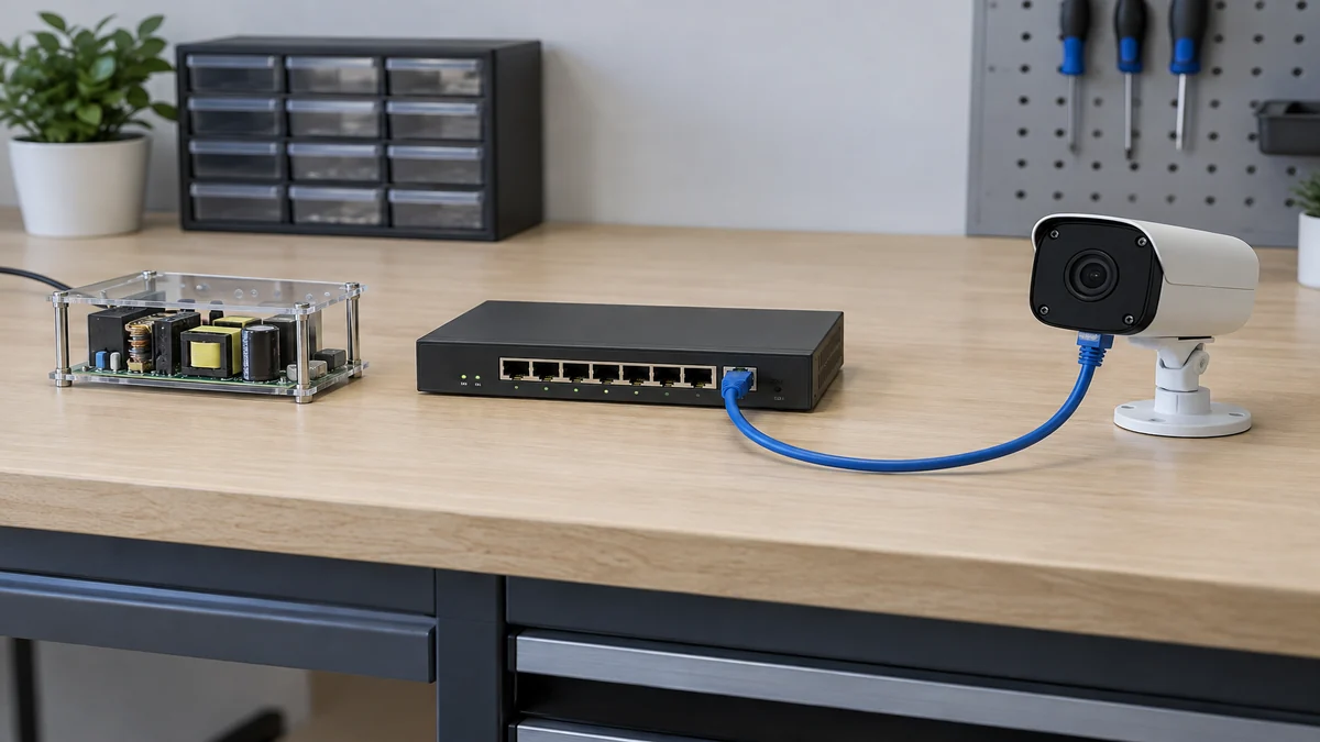
For directly powered DC cameras, confirm each model’s documented input range at its terminals, cable route, and highest-load state. Infrared illumination, heaters, or pan/tilt movement matter only when present on that model. Long runs make cable drop and fault isolation more consequential than the supply’s nameplate wattage alone.
Battery backup is a separate capability, not spare wattage
An ordinary open-frame AC-DC supply stops converting when its usable input disappears. Extra rated output does not keep the system alive. If the security design requires continuity, decide whether the protected function needs a central UPS ahead of the AC input, a DC-UPS and battery on the output side, or an integrated supply-and-charger arrangement. Those are different architectures with different loss, monitoring, battery-maintenance, and transfer behaviors.
For a concrete manufacturer example, Delta’s PJU open-frame DC-UPS announcement describes an identified series with an external battery connection, AC-OK and battery-low signaling, and defined battery-mode behavior. Those features belong to that series and specified variants. They must not be inferred from the words “open frame” or transferred to a conventional Powernexu 12 V AC-DC board. A separate battery charger and changeover design may be needed when the selected converter lacks them.
Backup time also depends on the load that remains active. A site may need controllers and network links during an outage but not every noncritical camera or display. Conversely, an access-control requirement may include a lock state or emergency release that cannot be treated as an ordinary DC uptime target. The door hardware, fire interface, local rules, and system designer must define the safe state. The PSU cannot settle that question on its own.
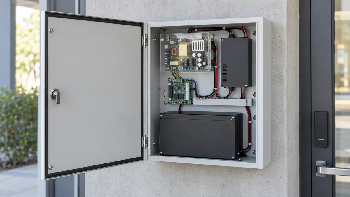
A battery capacity estimate should begin with the specified battery-mode load, permitted discharge window, conversion losses, temperature and aging assumptions, and the required duration. Multiplying a nominal battery voltage by an amp-hour label gives only a nominal energy starting point; it does not guarantee usable run time at the actual discharge current. Where battery supervision is required, a basic converter plus a battery placed across its output is not a substitute for controlled charging, isolation, protection, and fault indication.
The host enclosure completes the open-frame product
An open-frame board exposes components that an external adapter or fully enclosed PSU would shield. It belongs inside equipment with suitable barriers against contact, contamination, and accidental metal intrusion. Mounting standoffs, enclosure grounding, input-side protection, cable strain relief, separation between mains and low-voltage field wiring, and service access must be engineered into the finished product. A board-level certification or supplier claim does not by itself certify an assembled access-control cabinet.
Security cabinets may sit above doors or in wall recesses with little airflow. Assess the converter’s intake temperature with the cabinet closed. A board rated under forced air cannot be assumed to deliver the same continuous output in a sealed box; fan openings may also admit dust or unauthorized access.
Powernexu lists the GW-TO40WV12 open-frame 12 V supply as a board-level component for compact security-related equipment. Its published 12 V, 40 W description may be a starting point for a compatible low-voltage controller design; it does not establish fit for a particular lock, battery system, PoE switch, enclosure, or finished-system approval. That distinction is important when a parts list is being converted into a serviceable installation.
A small access panel shows where the limits appear
Consider an illustrative panel with a controller drawing 9 W, two readers drawing 3 W each, a local network interface drawing 5 W, and a 12 V actuator drawing 18 W while energized. These are hypothetical loads chosen to explain the accounting method, not Powernexu product data or typical ratings for all security equipment. The steady electronics total is 20 W. When the actuator is on, the example DC demand becomes 38 W before wiring losses and any additional margin. Whether a specific 40 W supply is appropriate cannot be decided from that arithmetic alone.
The actuator’s actual duty cycle changes energy use, but its peak current still affects voltage sag and branch protection. Continuous operation near a supply’s rating may also be limited by cabinet temperature or the manufacturer’s cooling condition. If that same panel powers another door, a recorder, or an illuminated camera, the assumed 38 W is no longer the complete bus load. If the camera is on a separate PoE switch, it must not be silently added to this 12 V board; the switch’s own upstream power path needs a different calculation.
Suppose a power failure occurs during an access event. If only the controller has battery backup while the actuator is on unbacked AC power, the controller may log the event but be unable to move the lock. If both are backed up, the battery and changeover path must support the relevant transient and the chosen safe-door behavior. If network communication is also required, the switch and upstream network equipment become part of the continuity boundary. This is why “hours of backup for the panel” is meaningless until the protected functions and actual loads are named.
The example also explains why a larger converter is not always the fix for a resetting controller. If measurement shows a sharp voltage drop only at a remote lock, the weak point may be cable resistance, a shared return, or an underspecified terminal. Increasing the PSU rating without changing that path may leave the disturbance unchanged. The useful measurements are taken at the supply output and at the affected device during the switching event, with the test performed under the installation’s authorized conditions.
Where the open-frame supply’s responsibility ends
The board converts its specified input into a regulated DC output under its documented operating conditions. The security system built around it determines how that output is distributed, protected, supervised, backed up, cooled, and made safe to service. In a simple indoor controller this may involve a short 12 V branch and a protected enclosure. In a larger installation it may involve separate lock circuits, PoE switching, recorder power, multiple monitored outputs, batteries, and emergency interfaces. Those are not interchangeable versions of one generic “security PSU” connection.
A useful design drawing therefore follows each function to its source: which board powers the controller, which source operates the lock, whether cameras draw from a PoE switch or a DC branch, and which of those paths remains energized after an input failure. Once that map is clear, open-frame voltage, continuous output, cooling method, mechanical format, and any backup accessory can be matched to the parts they actually serve. The result is a security power design with explicit boundaries rather than a large wattage number asked to stand in for them.