Industrial power supply EMI/EMC is not settled by finding an “EMC compliant” line in a supply datasheet. A switching supply can inject noise onto its input or DC output, while motors, contactors, radio transmitters, and electrostatic discharges can disturb the supply and the controls it powers. The outcome depends on the finished machine: cable lengths, filtering, enclosure bonds, load behavior, and the ports exposed to the outside. For a cabinet builder, the practical task is to distinguish noise the equipment emits from disturbances it must withstand, then follow the specific coupling path before changing the layout.
The supply is a component; the cabinet is the electromagnetic environment
A manufacturer’s emissions result describes a defined supply, load, grounding arrangement, and test setup. Moving that supply into a cabinet changes the environment. The DC harness may run beside encoder wiring, and the enclosure can provide a shield or a poorly bonded high-frequency return path. Adding a filter may not preserve the component’s bench result.
EMI is the interference problem; EMC is equipment operating in its intended electromagnetic environment without creating unacceptable disturbances for other equipment. Emissions and immunity are different sides of that requirement. A supply that behaves quietly in an emissions test can still power a controller that resets when a contactor operates. A controller that never resets may coexist with a cabinet that puts excessive noise onto an external cable.
Industrial location does not itself identify the applicable limit or test. The IEC description of IEC 61000-6-4 identifies it as a generic emissions standard for industrial environments, used where no applicable product or product-family emissions standard exists. Its companion industrial immunity standard, IEC 61000-6-2, addresses a different question. The governing product standard, market, installation environment, and ports of the final equipment still have to be determined; neither generic title is a universal certification attached to every industrial PSU.
Noise has a source, a route, and something that responds
A switch-mode supply changes current rapidly inside its conversion stage. The high-frequency energy can reach other equipment by conduction along wires, capacitive or magnetic coupling between nearby circuits, or radiation from a cable or enclosure opening. The converter is one possible source, not the only one in a machine. A variable-speed drive, relay coil, solenoid, or poorly terminated motor cable can create a disturbance that enters the PSU rather than leaving it.
On a pair of conductors, differential-mode current flows out on one conductor and returns on the other. Common-mode current travels in the same direction on both and returns through a chassis, earth, parasitic capacitance, or another path. The distinction matters because a filter element that opposes one mode may do little for the other. It also changes where a measurement should be made: a disturbance on the AC input, a DC output pair, and a shielded signal cable do not automatically share one cause or remedy.
Think of a supply feeding a PLC and several remote sensors. If a high-frequency current leaves the converter on the DC pair and returns through the metal cabinet, the long sensor harness may carry part of that current or radiate it. Shortening the DC loop or changing how the cable enters the cabinet may have more effect than replacing the PLC. If the disturbance arrives when a nearby contactor opens, the contactor circuit and its wiring are more plausible starting points than the PSU switching frequency. This is a causal model, not a claim that either path is present in a particular installation.
DC ripple measured at the output is not the same quantity as conducted emissions at an external port. An oscilloscope probe with a long ground lead can exaggerate a high-frequency spike; an emissions receiver uses a specified arrangement and bandwidth. A clean DC trace does not prove the cabinet meets an emissions requirement, and a noisy trace does not identify the affected port.
The cabinet layout decides which path becomes important
Three wiring regions deserve separate attention: incoming AC, DC distribution, and low-level sensor or communication lines. They have different current loops and susceptibility. Routing all three in one duct can put a noisy conductor beside a sensitive input for meters. Separation and deliberate cable crossings can reduce coupling. A right-angle crossing is often preferable to a long parallel run when cabinet geometry permits; it does not replace installation instructions or measurement.
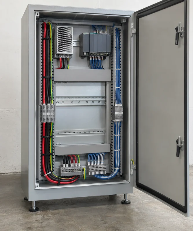
Keep the converter’s input and output wiring from doubling back across its switching area or any external filter. The return path is as important as the outbound conductor. A broad loop can couple magnetic energy into adjacent circuits; a long conductor can also become an effective radiator at frequencies far above the PSU’s fundamental switching rate. Bundling only the positive DC lead while its return follows another route enlarges that loop. In a multi-output cabinet, branch the DC distribution so high-current actuator loads do not force their transient return current through the reference used by a precision sensor.
The protective-earth conductor has a safety role that must not be compromised to cure noise. Functional bonding, cable-shield terminations, and chassis continuity can influence high-frequency return paths, but they must be designed within the supply manufacturer’s instructions and the applicable electrical safety requirements. A painted backplate, a loose door bond, or an unintended seam can make a mechanically solid enclosure electrically discontinuous at high frequency. Simply cutting earth, floating a protective connection, or relying on a signal shield as a protective conductor is not an acceptable EMC shortcut.
Long cables crossing the cabinet boundary change the problem again. A shield bonded at an entry point can help contain a disturbance, provided its termination and the connected device’s grounding arrangement are appropriate. A shield connected through a long pigtail may have much less high-frequency effectiveness than the same shield with a short, circumferential connection. But shield practice is not one universal rule: low-frequency ground differences, connector design, isolation, and the interface specification may constrain the termination. The real cable and port must be part of the analysis.
A filter is a boundary, not a magic box
An input EMI filter works across a defined boundary between an upstream power network and the equipment’s noisy circuitry. If unfiltered input conductors run beside filtered output conductors, noise can couple around the filter. The same bypass can occur through a nearby cable shield, poorly bonded enclosure panel, or shared wiring duct. Keeping the filter near the entry point and separating its line and load sides preserves the intent of the filter, subject to the product’s installation and safety instructions.
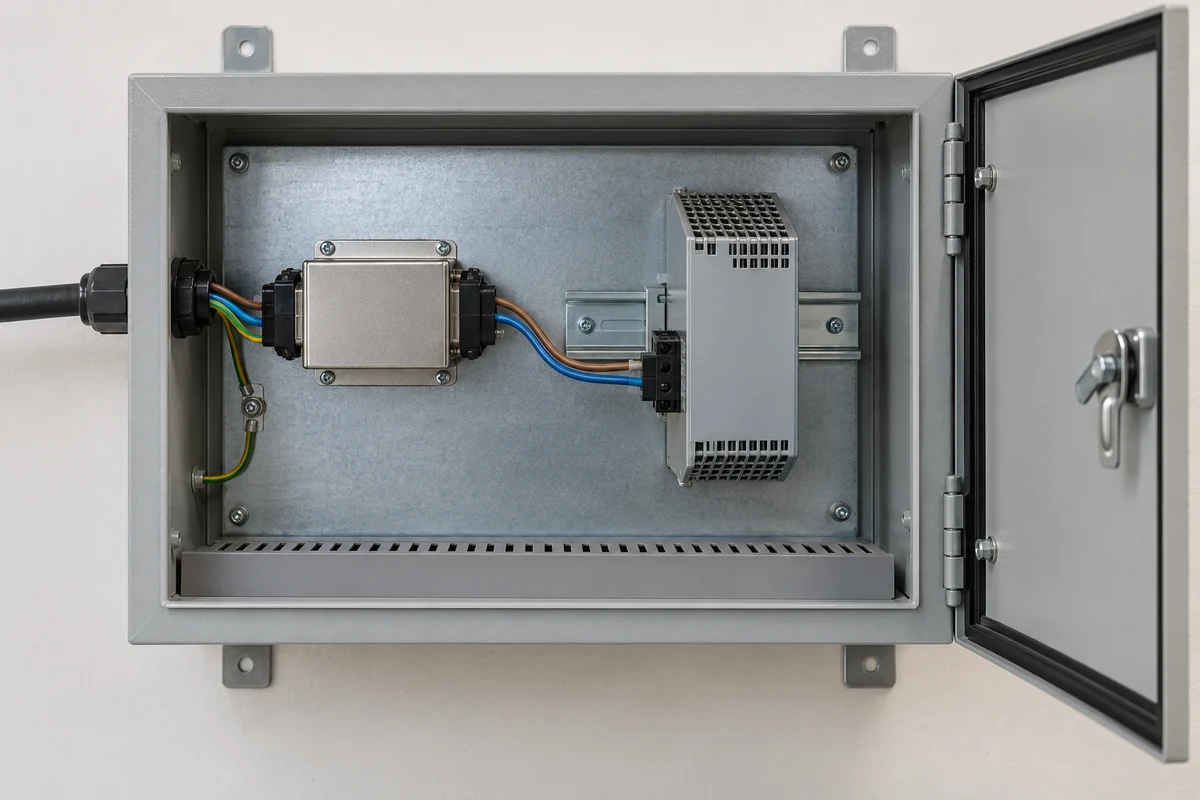
Extra filtering on the DC side also needs a reason. A ferrite, common-mode choke, or LC network may attenuate the troublesome frequency band, but the part must handle the actual current, temperature, and transient conditions. Additional output capacitance or a high-Q filter can interact with the PSU’s control loop or the load’s startup behavior. A ferrite added to an actuator branch cannot correct a disturbance coupled directly into an encoder line elsewhere. Select the component for the identified current mode and path, not because its package is labeled “EMI.”
Cabinet metalwork participates in the filter boundary. Mounting a line filter on an insulated bracket, or connecting its housing to the backplate through a long thin wire when the design expects a low-impedance chassis connection, can erode high-frequency performance. That does not mean every installation should copy one grounding diagram. The filter, supply, enclosure, and final-equipment safety design establish the permitted bonding arrangement. A change in cabinet construction or coating may require rechecking the same path.
A controller reset is an immunity symptom, not an emissions verdict
Suppose a PLC reboots whenever a large contactor releases. The first useful observation is the timing: does the DC rail dip, does the PSU report a fault, or does the PLC reset input change while the rail stays within its allowed range? If the supply input is interrupted briefly, hold-up behavior and the contactor’s upstream branch matter. If the DC output remains stable but a nearby sensor input spikes, the victim may be the I/O path. If the event occurs only when the contactor coil opens, suppression at the coil or its driver may be more relevant than a larger PSU. None of these conclusions follows from the word “EMC” on a label.
Surge, electrical fast transient, electrostatic discharge, conducted RF, and radiated RF test different stress mechanisms. A supply’s published immunity level may cover its own input or output ports under a stated test arrangement, while a finished controller has additional communication, sensor, actuator, and enclosure ports. A test report is most useful when it names the exact model, applied standard, port, severity, performance criterion, load, cable arrangement, and operating mode. The acceptable response during a test may differ: a temporary disturbance that recovers can be acceptable for one function but unacceptable for a safety-critical control task. That judgment belongs to the final product’s requirements.
An emissions failure asks a different question: where does unwanted energy leave the equipment? The external AC mains, a long DC feeder, and an unshielded communication cable can each be an exit route. Moving a measurement probe around the cabinet or separating cables temporarily can help localize a path, but a pre-compliance change should be confirmed in a representative configuration. An empty cabinet with short laboratory leads is not the same radiator as a machine with production-length motor and sensor cables.
Follow one realistic control-cabinet change through the system
Consider a cabinet that originally contains a DIN-rail supply and PLC. A redesign adds a variable-speed drive, a longer DC cable to a remote I/O station, and a metal door with a different bonding strap. No PSU model has changed, yet the electromagnetic system has. The drive introduces another switching source; the cable provides a new route; the remote inputs are potential victims; and the door construction changes the enclosure return path. Calling the PSU “EMC approved” answers none of those new questions.
Start with the observed problem rather than a preferred accessory. If the remote I/O fails only while the drive runs, check whether disturbance appears on its DC feed, its communication pair, or both. Examine the physical cable route and the drive manufacturer’s installation requirements. If the issue is an external conducted-emissions limit, inspect the defined measurement port and the wiring around the input filter instead. The same cabinet may need a routing correction for one symptom and a separate filter or enclosure change for another.
Replacing the supply is not the default fix. A lower-emission converter might help when it is the dominant source; it will not correct a drive cable beside a sensitive signal bundle. A higher-immunity PSU might ride through a disturbed AC feed but cannot guarantee that every PLC input or remote device stays unaffected. Locate the coupling path before assigning responsibility.
Read the EMC claim at the same boundary as the intended use
Datasheet entries such as “conducted emissions,” “radiated emissions,” and “immunity” are meaningful only with their test conditions. Look for the exact variant, operating load, input configuration, external filter if required, mounting surface, earth arrangement, cable length, and the standard or test level. Some suppliers test component supplies on a defined metal plane with a specified load. That is valuable evidence about the component, but it cannot predict every arrangement of a cabinet, harness, and adjacent drive.
For a finished machine, identify which ports cross the enclosure and where the applicable product or generic EMC requirements apply. The PSU’s documented behavior informs the design; the assembled equipment establishes what actually leaves its ports and how it responds to disturbances. If a cabinet revision changes the cable routes, filter placement, or bonds, the original component report still describes the component, while the machine’s electromagnetic behavior may have changed. This is why EMI/EMC work belongs in the physical integration plan, not only in the PSU part-number selection.