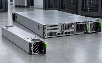
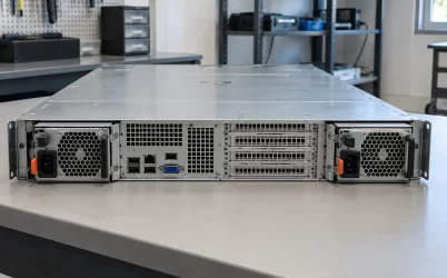
A blinking green light on a server power supply is not, by itself, proof of either a fault or normal operation. It can indicate that a module has AC input but is waiting in standby, that a redundant module is deliberately inactive, or, on a particular platform, that PSU firmware is being updated. The meaning depends on the exact server or PSU model, the indicator being watched, and sometimes the blink rate. First identify whether the light is actually on a PSU module rather than the server’s front status panel or a network port. Then read that model’s indicator table before changing hardware.
Which green light is blinking?
A server can present several green lights within a few inches of one another. A removable PSU may have its own input or status LED. The chassis may have a system-health indicator on the front, while a management controller has a separate heartbeat light on the board. Network ports often blink green to show link activity. A photograph of a green dot without its physical location is too little information to decode any of these. Even the phrase “power light” can mean a front-panel button on one machine and a PSU inlet indicator on another.
Begin with the physical component and the label in the service document. Record the server make and model, the installed PSU part or approved module family, which bay contains the blinking module, and whether the observed indicator is mounted on that module or on the surrounding chassis. A model’s front system-status LED table may not describe its rear PSU LED. Likewise, a generic CRPS module description cannot override the host’s approved control and management behavior. This identification work is not administrative fussiness: it prevents a healthy standby supply from being replaced because someone read the wrong table.

View the light over more than one instant. A slow regular blink, a faster regular blink, an occasional transition blink, and a flicker that changes when a module is touched are distinct observations. Do not infer a precise frequency from a brief glance or a low-frame-rate video. The useful record is whether the pattern is stable, which exact module shows it, what the host is doing, and whether anything changed when the indication began. No universal green-light frequency applies to all server PSUs.
One Intel example shows why blink rate matters
Intel’s server-system guidance on blinking green indicators provides a concrete model-family example. For the power-supply status LED it describes one blink per second as the PSU being off or in cold redundancy, while two blinks per second can identify a firmware update. The same article separately discusses a system-status LED that may blink green for other server conditions. Those distinctions apply to the Intel systems covered by that guidance, not to an arbitrary server from another vendor.
The first meaning can be surprising. A redundant module may be installed, connected to AC, recognized by the host, and ready to take load while not producing the main output during an energy-saving state. It is not necessarily a failed PSU. The other PSU may carry the present server load. The host decides when the reserve converter should become active; depending on the supported policy, greater load or loss of an active path can change the state. A green blink in that context tells a technician to examine the current module role before drawing a failure conclusion.
The firmware-update meaning calls for a different kind of restraint. If the exact platform documentation identifies a particular blink pattern as an update state, interrupting power or extracting the module merely because its light is changing can interfere with the process. That does not mean every fast blink is a firmware update. It means the observed frequency, maintenance window, management events, and specific vendor instructions matter together. If the light has a different documented meaning for the installed generation, the Intel example is not a substitute.
Notice that the same color can exist on two separate indicator classes. A system-status light on the front may report the condition of the entire server, including redundancy or another degraded component. A rear PSU status light reports something narrower about a power module. Combining those tables into one “green blink code” produces false interpretations even within a single manufacturer’s equipment. The component location must accompany every statement about the light.
Other manufacturers make the boundary clearer, not universal
Lenovo’s published LED table for the ThinkSystem SD550 V3 gives another specific example: slow blinking green on its power-supply status LED describes a supply in standby with AC present, including cold-standby or always-standby conditions. A solid green state has a different meaning in that table. This is useful evidence for that model, not permission to label a green blink on every Lenovo machine as standby. The exact server generation and LED position remain part of the definition.
A Supermicro system manual provides yet another formulation for one of its servers: a blinking green PSU light can mean that the supply is plugged in while the system has turned it off. That resembles a standby interpretation, but the wording and available modes belong to the particular system. Supermicro has also documented an intermittent green indication in a specific support case where a module was not fully seated against its power distributor. A regular programmed blink and an irregular connection-related flicker should not be conflated. Neither example makes a general diagnostic rule for all Supermicro supplies.
These examples do not form a cross-brand conversion chart. They show why the answer must start with a model-specific document. Firmware generation, hot-plug cage design, redundant-power policy, and indicator placement can change what is observable. Two modules that look alike from the rack aisle can have different approved operating modes. Color is only one symbol in a local status language; timing and context provide the rest. If the exact manual cannot be found, the honest interpretation is “meaning not yet established,” not a guess borrowed from a similar-looking server.
A standby blink is a power-state report, not a capacity promise
When a vendor’s documentation does identify blinking green as standby or cold redundancy, it answers a narrow question: the module is in a designated low-output state. It does not prove the server has enough surviving capacity after a failure. An active PSU might be carrying the host alone at the present load, yet the reserve may be needed once accelerators or drives enter a higher-demand state. Management may move the reserve into active service before any fault occurs. The blink can disappear because of normal policy, not because the PSU was repaired.
Conversely, two physically installed supplies do not automatically mean the host is protected against losing either one. A pair may be operating in combined-capacity mode when one module cannot sustain the permitted workload. The PSU LEDs may look reassuring while the platform reports redundancy unavailable. Read the host’s power configuration and capacity state rather than treating a green indicator as an availability certificate. Electrical independence of two upstream feeds is a separate question again; the LED generally cannot establish that the cords lead to different protected sources.
There is also a difference between “server shut down” and “cold redundant during operation.” Some platforms keep AC and an auxiliary rail available when the host is off, so a PSU can be present and controlled even though the main compute load is stopped. Other systems define standby differently. A light that blinks while the operating system is down should be interpreted against the host power state, not simply against the absence of fan noise. One PSU may be idle because the whole server is off; another may be a reserve while the server continues running. The same visible behavior can accompany very different operational situations.
Monitoring helps, but it too has a scope. Per-module telemetry may distinguish present, input valid, output active, standby, warning, and failed states when the platform supports those reports. A rack PDU sees AC draw at its outlet, which may be small for a standby module, but it cannot directly decode the PSU’s internal reason. A front status LED summarizes still another layer. Combining these sources can resolve an ambiguity, provided their timestamps and meanings are read from the relevant platform documents rather than assumed to agree automatically.
When the pattern changes unexpectedly
A familiar standby blink that begins after a supported efficiency-policy change may be expected. A new blink accompanied by a server alarm, lost redundancy, failed start, input-power event, or unusual fan behavior deserves investigation. The change in surrounding state matters more than the color alone. Preserve the management event log before clearing alarms, and compare the indicated bay with the server’s current PSU configuration. If one module is said to be missing or mismatched, a green light on a neighboring module does not explain the missing unit.
Observe the source side without intrusive electrical work. Confirm which rack outlet and cord serve the affected bay using the site’s approved operating procedure, and check whether the source reported an event at the same time. A PSU LED can be dark because AC is absent, but a blinking green light does not prove that source voltage remained valid through every load change. PDU and UPS logs have their own sampling intervals; their absence of an alarm is not a high-speed waveform measurement. A visible cord connection likewise does not establish a sound mating contact.
Mechanical questions require caution. A poorly seated hot-plug unit, damaged bay, or unsuitable replacement can produce a status that is not fixed by decoding the blink. Reseating or exchanging a module should follow the exact host manufacturer’s supported service procedure, with remaining-load capacity and hot-swap eligibility established first. Do not remove a module from a system merely because another identical-looking module has a steady green light. Do not open a PSU enclosure or probe its live contacts to determine an LED’s meaning.
A regular pattern that the manual defines as normal still deserves context if the server is not behaving normally. The indicator may accurately report “standby” while the real problem is that the host never requests the main output, rejects a module, or cannot progress through startup for an unrelated reason. A diagnosis then belongs to the host’s event sequence, not to the color of the PSU lamp. If the manual instead defines the pattern as an update or warning, respect that specific instruction. Replacing a module without reconciling the reported host state can turn a readable symptom into a more confusing one.
The answer belongs to the exact light on the exact server
To answer “why is the green light blinking,” name the indicator, server family, module family, blink rhythm, and current host state in one sentence. A documented slow blink on one machine may mean an AC-fed standby PSU; another documented rhythm on a particular Intel system can indicate firmware activity. A front system-health light can communicate a broader condition than either. If a pattern is irregular or changes with an alarm, the cause remains open until model-specific events and input status are checked.
The practical outcome is not a universal chart but a defensible interpretation: this light, on this component, in this power state, matches this entry in the manufacturer’s current service guide. That answer can tell an operator whether to leave a healthy reserve alone, let an update complete, or investigate a new fault. Green itself cannot make that distinction.