A server PSU that repeatedly turns on and off is not necessarily failing in the same way on every cycle. The useful question is why another attempt begins without an operator: a converter may automatically retry after protection, a server controller may issue a new power request, or the incoming supply may recover after an interruption. Those mechanisms have different reset conditions. A module that latches off cannot keep restarting on its own until something clears the latch; a timed auto-retry can. Watch one complete off interval, including the transition that ends it, before treating the rhythm as evidence of a bad PSU.
The next start, not the last shutdown, defines the loop
One aborted start is an event. A loop contains an additional action: something restores the conditions for a new attempt. That distinction is more useful than counting fan spins. A fault can remove the main output, but the next start requires an internal recovery timer, a reset of a protection latch, another host power-on command, or the return of a missing source. Unless that initiating action is identified, “keeps turning on and off” describes only what the observer sees.
Consider two superficially similar sequences. In the first, a supply drives its output briefly, detects overcurrent, shuts the output off, waits, and tries again while the host continuously requests power. In the second, the supply remains capable of output, but the host drops its enable request after a platform fault and later asserts it again. Both can make chassis fans twitch at regular intervals. Their control loops differ: the first belongs to the converter’s protection design, while the second belongs to the server’s power policy. An AC interruption adds a third reset path, but it is not necessary to invoke that possibility for every blinking module.
A useful observation is whether the whole machine, a single hot-plug module, or merely a fan changes state. Redundant supplies can operate in active and standby modes, and fan control can change without a host power cycle. The word “on” might mean AC present, a standby rail available, a main output enabled, or the operating system running. Establish which state is actually oscillating. A server that boots, runs, and later restarts belongs to a different timing class from one whose main power pulses before the host can initialize.
Auto-retry and latch-off produce different repeated behavior
Many switching converters respond to excessive output demand with a protection state. In an auto-retry or “hiccup” response, the controller limits the duration of a failed attempt, pauses, then attempts to start again. If the overload persists, the output rises and falls repeatedly. The pause reduces average fault stress, but it is not a diagnosis of which part of the installed power path is overloaded. A fault on a distribution board or downstream rail can make a healthy removable module exhibit this behavior.
Other protection designs latch the affected output off. A latch requires a defined reset action; simply waiting may not restore it. The distinction must be read from the exact module and platform specification. The Intel R2000WF product-family technical specification, for example, specifies in its DC-input PSU section that main-output overcurrent latches off and that toggling PSON# or interrupting the DC input clears the latch, whereas the standby output auto-recovers after its overcurrent condition is removed. Its AC-input PSU section has its own reset requirements, so the DC-input wording must not be applied to an AC-fed module. These are requirements for that family, not a generic server-PSU pinout or a universal recovery schedule.
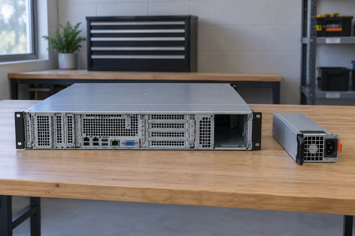
This example exposes an important trap. If a latching main output repeatedly comes back, something outside that latch may be resetting it between attempts. A controller that deasserts and reasserts the power-on signal can create a sequence that looks exactly like autonomous converter retry. Removing and restoring input can do the same. Conversely, a continuously asserted host request together with a documented auto-retry supply is consistent with converter-driven cycling. Neither inference proves that the converter is defective; the repeated demand could originate in the load.
Protection categories also need not share a reset rule within one supply. The same Intel specification describes automatic restoration after an overtemperature condition cools, while requiring margin against oscillation during thermal recovery. Thermal mass usually makes this a different pattern from a rapid electrical retry, but no universal number of seconds separates them. A warming module may run longer on its first attempt than on later attempts, or its off time may change as the assembly cools. Such drift is more informative than a single measured interval, provided the system is not deliberately left to cycle for observation.
What an interval can and cannot say
A highly regular short pause suggests a timer somewhere in the loop. It does not name that timer. A converter’s retry circuit, a BMC power-sequencing timeout, a watchdog, an outlet controller, and a UPS recovery policy can all create repeatable intervals. The interval is also measured at a chosen boundary: fan stop to fan restart is not necessarily output-off to output-on, and neither is necessarily the time between host commands. Describing the visible cadence without naming the observed device creates false precision.
The first cycle deserves special attention. If the initial on period lasts until a workload begins and every later pulse is brief, the fault may be linked to a load transition or a thermal state inherited from the first run. If every attempt has the same brief duration from a cold start, a fixed sequencing or protection condition is more plausible. If the server fully boots between shutdowns, a software or management recovery policy becomes possible in a way it is not during a sub-boot pulse. None of these patterns is an LED code; each identifies a class of event worth correlating with platform records.
The observed rhythm may also be apparent rather than electrical. A PSU fan can cycle under a fan policy while the DC output remains stable. A spare module in cold redundancy can move between operating states while its partner carries the system. An LED may blink to communicate a condition without implying that the main rail follows it. The simplest discriminator is whether the host workload and management connection actually lose power. Where the host stays up, calling the phenomenon a repeated server power failure leads the investigation away from the component that changed state.
When the server itself supplies the next power request
A platform can deliberately restart after a watchdog expiry, firmware decision, or configured recovery action. That does not make every reboot a watchdog event. The distinguishing feature is that the host had enough control state to issue a new request. On relevant Dell platforms, for example, the iDRAC Service Module automatic system recovery feature can be configured to reboot, power cycle, power off, or take no action after its timer expires. That illustrates a class of host-initiated repetitions; it does not establish that an unknown server has that policy enabled.
A true power cycle ordered by the host is also different from an operating-system reboot. A reboot may leave PSU main output continuously available while processors and software restart. A host power-cycle action intentionally passes through an off state, although standby management may remain alive. The front panel alone often does not separate these cases. If management records show a commanded action immediately before each main-output transition, interpreting the PSU fan as the initiator reverses the causal order.
Early platform sequencing can produce a retry loop even when the operating system never loads. The host requests main power, tests a condition needed to continue, returns to standby, and later tries again according to its own firmware policy. Another platform may stop after a single failed attempt. Because these policies vary, a repeated pulse does not prove that the server “keeps pressing the button” either. The exact event text, model documentation, and timing of the command relative to output loss matter more than a generic list of possible failed components.
Repeated source recovery is a different reset mechanism
Input returning after a dropout can start the cycle again without either converter auto-retry or a new manual button press. Whether a server stays off, returns to its prior state, or powers on after AC recovery depends on its configured platform behavior. A switched PDU outlet, unstable UPS output, intermittent connection, or facility event can therefore produce a repeated server-level sequence. The PSU is the visible device reacting to source loss, but the next start is initiated upstream or by the platform’s response to restored input.
The useful evidence is not a static reading that shows voltage at the outlet between events. It is whether source state changes at the moment the server begins another attempt. A PDU or UPS event record may resolve a controlled outlet operation or input loss; a slow dashboard may miss a brief disturbance. A log entry from the server can indicate that input was lost at its own inlet, but it cannot by itself say whether the interruption began at the cord, outlet, UPS, or facility source. Each observation has a physical measurement boundary.
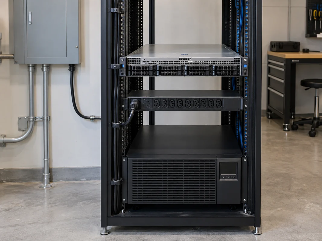
With two power cords, the patterns are not automatically symmetric. One feed may disappear while the other sustains the host; the affected module may seem to cycle while the server never does. Both modules may lose input together because their cords share a source. Neither observation is a verdict on redundancy without knowing the actual cabling and the platform’s active-module state. The distinction is narrow but important here: determine whether restored input triggers another attempt, not whether the installation meets every possible redundancy objective.
Electrical source investigation belongs to qualified personnel using the site’s approved procedures. The article’s timing logic does not authorize opening a PSU, bypassing protective devices, probing a live backplane, or improvising an adapter. Repeatedly cycling an unstable feed to “see if it happens again” can create additional service and data-integrity risk. Existing alarms and permitted instrumentation are preferable to provoking more events.
Two recovery loops can create one visible rhythm
The converter, host, and input system do not have to act independently. One loop can interrupt or reset another. Suppose, hypothetically, a converter is designed to retry an overloaded output. The host sees the resulting power-good loss, abandons its own start, waits, and later makes a new power request. The module’s internal retry delay might never finish because the host removes its enable request first. The visible fan-stop interval would then follow the host’s timing, even though an output-side overload began the sequence. Measuring that interval alone would assign the cause to the wrong controller.
The reverse interaction is possible too. A server may be configured to retry a failed start, but an upstream outlet controller can remove power before the server’s own delay expires. When the outlet returns, the host follows its AC-recovery policy and begins again. A rack observer sees a repeatable cycle without knowing which timer was interrupted.
For that reason, distinguish the action that ends the off interval from the fault that began it. An input-restoration record followed by module activity identifies a different chain from a host power-on command made while input remained present. A documented main-output latch that clears only after a control transition cannot itself generate a fresh output attempt while its reset condition remains absent. A documented auto-retry design can attempt again without a new host command, but only while the required input and enable conditions persist. Where those states are not observable, the honest diagnosis is narrower: the server cycles repeatedly, but the initiator remains unproved.
A service team should not leave the machine cycling to collect a prettier rhythm. Repeated starts can stress the installed load and interrupt data or service even when the PSU survives. Capture a short, permitted observation window, then use the vendor’s supported procedure for the controller or electrical boundary implicated by the last known transition. The useful outcome is not a guessed failed part. It is identifying which recovery mechanism is capable of starting the next attempt—and whether that mechanism is behaving as designed.