A multiple-output open-frame power supply may show the right voltage on its main rail while an auxiliary rail moves when a different load changes. That is not automatically a defective converter. Some multi-output designs regulate one output directly and let other outputs follow it through shared magnetic and control behavior. The datasheet may require a minimum load on a particular rail, or specify auxiliary-rail accuracy only for certain combinations of load. Other designs give each output a separate regulator and behave differently. The useful question is not merely how many voltage labels appear on the board. It is which output the feedback loop watches and what happens to every other output across the machine’s real operating states.
One control loop can serve several output windings
An isolated switching converter transfers energy through a transformer. A low-cost multiple-output implementation can use more than one secondary winding to obtain different nominal DC voltages. After rectification and filtering, those windings feed separate output rails. Yet a shared switching stage does not necessarily receive a separate error signal from every rail. A designer may choose one principal output as the regulated reference and use the converter’s switching control to hold that output near target.
When the principal rail changes, its feedback loop responds by changing how the shared power stage operates. The auxiliary rails are coupled to that same change. They may therefore move even when their own loads have not changed. Conversely, an auxiliary load can alter the electrical balance of the transformer and its rectifiers without receiving an independent corrective response. The amount of movement depends on the actual topology, winding design, output filters, loading and control method. A nominal voltage printed beside an auxiliary connector says little about the permitted movement.
TDK-Lambda’s manufacturer explanation of multiple-output cross-regulation describes a specific simple triple-output arrangement: the principal output has feedback while two others are semi-regulated. It also describes alternative designs with additional conversion or post-regulation. Those are illustrative architectures, not proof that every open-frame product uses the same transformer or the same minimum-load rule. An exact datasheet and, where necessary, the manufacturer’s block diagram establish which case applies.
This control distinction matters most when loads do not rise and fall together. A machine might keep its logic rail alive while enabling motors later. A communication module may sleep while sensor electronics stay active. A peripheral rail can be heavily loaded during startup and lightly loaded after boot. If one rail’s permitted voltage assumes that another rail carries a stated load, the system must satisfy that assumption in every state that matters, not just at the maximum combined wattage.
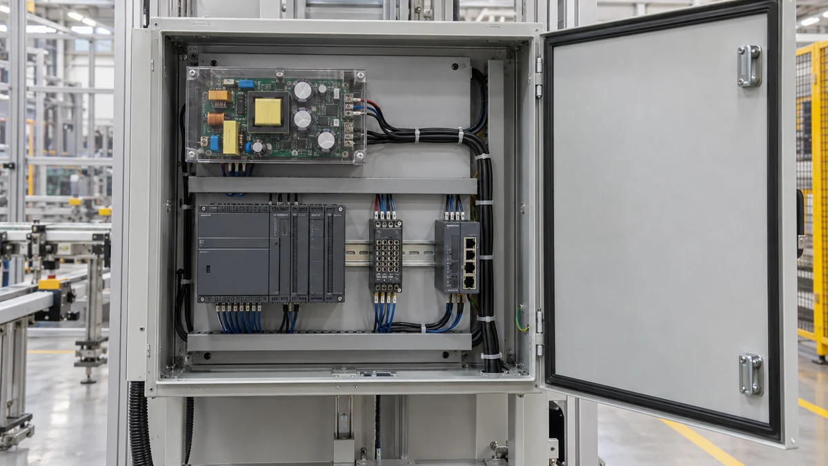
Why a minimum load may appear in the specification
A minimum load is a documented operating condition, not an invitation to add an arbitrary resistor to every open-frame board. In a shared converter, the main control loop may reduce its switching effort when its regulated output has almost no demand. Under that condition, an auxiliary winding can receive too little effective energy for its specified voltage while the auxiliary load is still substantial. Other load combinations can drive an auxiliary voltage upward. The exact direction and magnitude are design-dependent; a generic percentage cannot describe all models.
Consider a controller that needs a small amount of power from the principal rail during normal operation but shuts most of that circuitry off overnight. A second rail continues to power a communications link. The overnight state could be more difficult for a semi-regulated auxiliary output than a busy daytime state, even though total watts are lower. A bench check performed only with every rail loaded near its nominal rating would miss that condition. Startup can reverse the order: the communications rail might need to rise before the controller begins loading the principal output.
The datasheet wording must be read precisely. A minimum-load line might apply to one output only, to several outputs, or to a defined combined load. It may be required for regulation accuracy rather than for converter survival. It may also change with input voltage or temperature. A statement that a supply can operate at no load on one output does not establish that every other rail keeps its tightest tolerance in that state. The regulation table, test conditions and notes should be interpreted together.

Artificial loading can be a poor fix. A fixed bleed resistor wastes power and adds heat whenever the machine is energized. It might satisfy a minimum-load condition at one voltage and temperature yet leave the larger issue—a rail-dependent architecture mismatched to the load sequence—untouched. If a load is genuinely needed, its value and thermal rating have to come from the exact supply documentation and the equipment design. In many cases an independently regulated multi-output board or a single main bus with local DC–DC conversion is the cleaner architecture.
Cross-regulation is not the same as ordinary load regulation
Load regulation describes how one output changes as the load on that same output changes, under stated conditions on the other outputs. Cross-regulation describes how one output changes when the load on another output changes. The distinction sounds small but changes the test. A technician can hold the auxiliary load fixed, vary the principal-rail load, and observe whether the auxiliary voltage shifts. Repeating the test in the other direction may reveal different behavior because the feedback loop is not symmetric.
One output’s meter reading is never the complete result for a multiple-output board. A main rail can remain tight precisely because it is the rail being corrected, while a secondary output is the one that drifts. Measuring only the best-regulated output can therefore hide a machine-level problem. The relevant observation is every required rail at its load terminals during the same state, with enough time resolution to catch startup or a pulsed transition if those states matter to the equipment.
Cross-regulation specifications may appear as a percentage, a voltage range or a test note stating which rails were loaded. Compare them with the load’s actual tolerance in volts, not just with the supply’s nominal label. A device that accepts a wide input range may tolerate a variation that would reset a tighter analog or logic circuit. Likewise, a voltage that is acceptable at the supply connector can fall outside the load’s range after cable and connector loss. That downstream drop is a separate phenomenon; it should not be mislabeled as cross-regulation.
Load combinations reveal more than a total-watt figure
The total output rating is a ceiling under specified conditions, but it does not say how the watts may be divided among rails. Individual current limits, grouped limits, thermal conditions and cross-regulation notes can all constrain a combination that is below the total rating. A board with four labeled rails is especially easy to misunderstand if someone adds four independent maximum-current figures and assumes they can all occur together.
A useful comparison follows the equipment sequence. At power-up, which rail has the earliest load? After controllers boot, which loads remain? During a motor or radio transmission event, which rail changes first? What happens when a peripheral is disconnected or enters sleep? The aim is to identify a few electrically different states, not to create a generic checklist for every device. Two states with the same total watts can stress a shared converter differently when the load distribution across windings differs.
For example, a board can supply the same combined output power in two configurations: one with the principal rail heavily loaded and one with most demand on an auxiliary rail. The feedback loop sees those configurations differently. A published combined wattage may cover both only if the per-rail and minimum-load conditions also permit them. Without a valid load-distribution table, a numerical claim that the second configuration is safe would be invented. The relationship must be taken from the specific product’s specification or verified with the manufacturer.
Transient states matter as well. Downstream capacitors charge at different times, control circuits may enable outputs in sequence, and motors or radios can create short demand steps. A slow multimeter reading after the machine settles can conceal a rail dip that occurred while a processor was booting. Observing all relevant rails during those transitions can separate a steady cross-regulation issue from an inrush or protection event. The permissible method and test setup depend on the equipment; this is not a recommendation to probe exposed mains or live open-frame conductors.
Independent regulation changes the answer
Not every multiple-output supply has a “master” rail followed by loosely controlled auxiliaries. A product may use separately regulated converter stages, post-regulators or other control arrangements that keep each output within its own specified range over a wider set of load combinations. Those designs can reduce or eliminate a minimum-load requirement that exists on a simpler shared converter. They can also add components, conversion losses, cost or thermal concentration. Their advantage is not a universal numerical accuracy claim; it is the documented ability to meet the required rail behavior for the intended load states.
A single-output AC–DC board followed by local DC–DC regulators is another route. It moves output-specific regulation closer to the consuming circuits and may allow different sequencing or fault separation. Yet the common upstream bus still has a power and transient limit. A fault or undervoltage on that bus can affect every downstream regulator. The best architecture follows the equipment’s actual rail tolerances and dependency pattern, not the assumption that four native outputs are always simpler or that four local converters are always safer.
These choices also affect maintenance. Replacing a board with the same nominal rail voltages but a different minimum-load rule can create failures only in standby or unusual startup states. An apparently compatible substitution may pass a quick powered test and fail later when one load is disabled. Preserve the exact variant and the relevant regulation conditions when qualifying a replacement; a connector that mates correctly does not guarantee equivalent cross-rail behavior.
The rail that moves tells you where to look
If an auxiliary output changes whenever the principal load changes, first compare that operating point with the exact supply’s cross-regulation and minimum-load conditions. If it falls outside them, the explanation may be the selected architecture rather than a defective unit. If the condition is allowed yet the output is out of tolerance, the evidence points toward a product fault, a distribution loss, an incorrect load assumption or a measurement problem that needs competent investigation. The main rail’s stable voltage does not settle that question.
Conversely, when every rail moves together, look beyond a single auxiliary winding: the AC input, common conversion stage, shared current limit or downstream bus event may be involved. A change confined to one load terminal can be caused by the connection to that load rather than by cross-regulation inside the board. These are fault-location distinctions, not universal symptom codes. No single rail pattern proves an internal component failure without the model’s design information and a controlled observation.
The practical value of understanding cross-regulation is that it changes the original question. “Does this multiple-output open-frame supply provide all the voltages?” is too weak. The better question is whether every required voltage remains inside the load’s range when the other rails draw the currents they will actually draw—especially at startup, light load and changing demand. A board whose documentation answers that question can be integrated deliberately. A board that merely lists several nominal outputs cannot.