A “1U 12V server power supply” combines two descriptions that answer different questions. The 1U label concerns the server’s rack height and the space available for its power bay. The 12V label usually describes a main DC output bus, not the input feed or every voltage used by the motherboard. Neither label identifies a complete interchangeable PSU. A usable replacement or new design must fit the actual bay, mate with the installed power-distribution interface, provide the required main and standby outputs, and survive the chassis airflow and electrical load. The two labels are a useful starting filter, not a compatibility statement.
A rack-unit height is not the PSU-bay height
A 1U server occupies one nominal rack unit, but its internal usable height is less than the external mounting interval. Sheet metal, lid clearance, mounting rails, air seals, and the mating connector all consume space. A slim PSU that fits the nominal rack pitch can still strike the lid, fail to enter its guide, or sit at the wrong height for the backplane. Its width and depth matter too: two power bays beside network ports and system fans have a different envelope from one fixed supply with cables exiting inward.
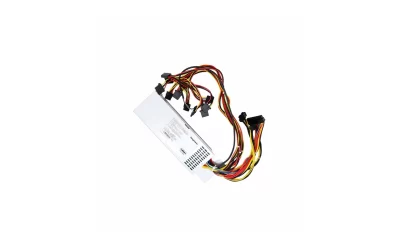
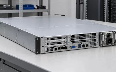
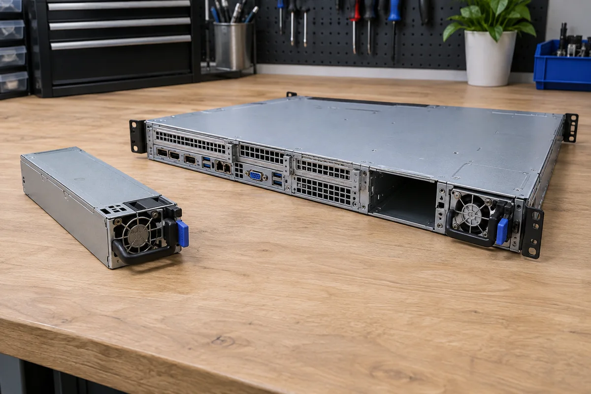
The picture places a loose low-profile module beside a complete 1U chassis. It illustrates the physical comparison, not approval of that module for that bay. The decisive dimensions are the installed bay opening, guide rails, insertion travel, handle clearance, rear-panel cutout, and connector position after full insertion. Those details are usually tied to a chassis or approved module family. A seller’s photograph showing roughly the right shape cannot establish them.
Height can become more restrictive during service than during installation. A module may slide into an empty chassis on a bench yet become difficult to extract once the server is mounted between neighboring equipment, rack cable arms, and rear PDUs. A rear-facing handle needs an accessible removal path. If a 1U design relies on hot-swappable supplies, that path is part of the operating architecture, not merely a technician’s convenience.
Some CRPS families use a compact body intended for a 1U-class power bay. The Advanced Energy CRPS series is one documented example of a common 1U-form-factor family with stated input and airflow options. Its published envelope illustrates how a module family can be standardized within its own interface; it does not imply that every 1U host accepts any CRPS module or that all members share every electrical limit.
“12V” describes a bus, not the whole power system
Many server supplies deliver a high-current 12V main rail to a distribution board or motherboard. Regulators near processors, memory, and other loads then create lower operating voltages. Storage, fans, and add-in hardware may receive power through separate connectors or local conversion stages. A server can therefore be accurately described as using a 12V PSU without its processor, memory, or all peripheral connectors operating at 12V.
Identify the exact terminals to which the 12V claim applies. On an AC-input PSU, the power inlet is not a 12V input. The 12V designation may refer to a main output rail at a card edge, a cable harness, or a connector leaving a PDB. A DC-input assembly may be described using its own input voltage and a different output architecture. Mixing those boundaries can lead to purchasing an electrically unrelated component even when both listings contain the phrase “12V server power supply.”
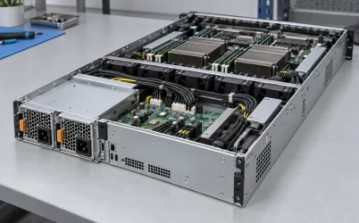
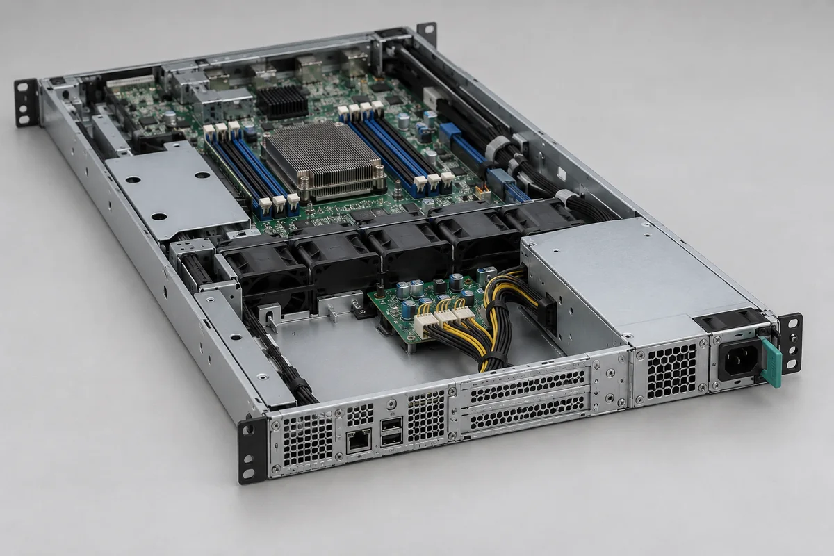
The open-chassis illustration shows a representative PSU-to-board-to-motherboard relationship. Its visible harness is not an exact pinout for a commercial model. In a real system the host’s drawing must separate main output, return, standby, sense, enable, power-good, and any communication contacts. The direction and role of each contact are more important than the fact that one rail is nominally 12V.
Standby output is particularly easy to miss in a compact server. Management electronics may need power while the main bus is disabled. A supply with the right 12V main rating but the wrong standby function, contact position, or power-state behavior may not start the host. In a platform with a BMC, a missing status or identification route can also appear as a PSU fault even when the converter itself is able to deliver power.
The mating interface decides whether the module belongs there
A removable 1U PSU commonly mates to a power-distribution board or backplane. The connector carries more than bulk DC current: the design may include dedicated returns, standby, control, present, fault, or management contacts. Even visually similar card-edge arrangements can differ in contact assignment, sequencing, keying, and mechanical datum. A replacement cannot be accepted from voltage and outer dimensions alone.
Return contacts deserve as much attention as the positive 12V path. Current leaves the supply through a defined set of contacts and returns through another set; a connector with the wrong number or placement of return contacts can concentrate heat or create a voltage difference between boards. A remote-sense pair, if the system uses one, may regulate voltage at a selected downstream point rather than at the PSU terminals. Joining it to the wrong contact is not equivalent to moving an ordinary power wire. The interface drawing must show how the host expects the power and sense paths to meet.
The chassis and module also determine whether the mating action is mechanically repeatable. Rails should guide the module to the contact position without using the connector as a structural alignment tool. The latch must hold it seated under vibration and service handling. If the assembly includes an interlock or staged contacts, their order has to be preserved by the actual pairing. These are host-dependent requirements, not universal features of all 1U supplies.
When a fixed PSU uses a cable harness instead of a blind-mate interface, the problem changes. Cable length, routing around the fan wall, connector keying, return paths, and available bend radius matter. Moving from a fixed supply to a hot-plug module is not a simple box replacement; it can require a different cage, PDB, rear panel, and management behavior. The article’s “1U” qualifier makes that architectural difference more urgent because there is little unused space in which to hide adapters or excess cable.
A product page can be a starting point for a candidate search. Powernexu has an HK1300B-S1 product listing, but the listed output, form factor, dimensions and chassis suitability require exact-model manufacturer verification before they can be used as technical specifications. The listing does not authorize substitution into an unknown host. Match the installed module’s exact part number and revision, the host’s approved list, connector system, power-distribution assembly, airflow direction, and supported control behavior before treating any listed module as a replacement.
Twelve-volt current becomes concentrated in a narrow bay
At a given output power, lower bus voltage means higher current. A hypothetical 12V bus delivering 1,200W carries 100A at the PSU output, before allowing for branch distribution and dynamic load changes. This is arithmetic, not a rating for a specific product. In a shallow 1U assembly, that current may pass through compact contacts, short busbars, and limited PCB copper near hot exhaust air. The electrical route and cooling route meet in the same crowded region.
The DC output rating printed for a module may also depend on its input conditions. A unit advertised for high power at one mains voltage may have a lower permitted output at another. This is not a universal 1U rule; it is a model-specific operating limit to read from the actual product document. What matters to the server is whether the available 12V current at the installed feed can sustain the loads that remain after any required redundancy event.
Two 1U modules do not automatically make their nameplate wattages additive usable capacity. In a 1+1 arrangement, the system is normally designed so one surviving module can support a defined operating state. The PDB, connector, and downstream bus must also tolerate that state. If both modules are needed to run at full performance, the system may need documented power limiting or may lose full availability after one fails. Those policies belong to the platform, not to the generic 12V label.
A more helpful load description separates sustained demand, startup demand, and short excursions. Storage devices, fans, CPUs, and accelerators need not reach their peaks at the same time, but assuming that they never do is not a safe substitute for the host’s power budget. A 1U server often has fewer cooling and expansion options than a taller chassis, so a change in load population can alter both current and inlet temperature at the PSU bay.
Airflow direction can invalidate an otherwise plausible fit
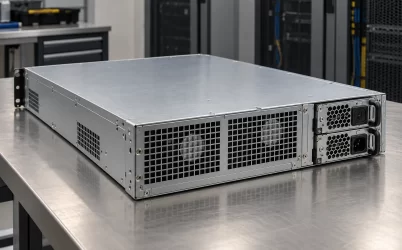
A 1U server usually uses a tightly controlled airflow path. The fan wall, PSU fan, inlet grille, baffles, and rear exhaust all influence the temperature seen by a slim converter. Two modules with the same body dimensions may move air in different directions or expect different chassis assistance. If a replacement exhausts against the system flow, it can recirculate warm air even while the electrical connector appears compatible.
Imagine a module that starts a server cleanly on a bench but reaches its thermal limit after the lid is closed and the rack warms. The discrepancy need not mean the advertised output rating was false: the module may have been rated with a different inlet temperature or airflow direction from the installed bay. The relevant air temperature is measured where the PSU takes in air, not merely at the front of the rack. A neighboring module, cable bundle, blanking panel, or obstructed rear exhaust can change that local condition without changing the server’s nominal 1U height.
The PSU can also compete with other components for the limited rear-panel area. A larger fan grille might displace network ports or block a cable route. A deep module can protrude into the fan wall or motherboard region. In a redundant layout, each bay needs enough air when its neighbor is removed or failed; an empty bay may require a blank or seal to prevent bypass. These relationships are visible in the physical chassis, but the permissible inlet temperature and derating remain specific to the selected module.
Thermal density is why “1U 12V” should not be read as a performance class. It says nothing about conversion efficiency, loss at the actual operating point, fan acoustics, permitted ambient temperature, or maximum output under that temperature. A compact module may be electrically capable at a bench condition but limited by the host’s inlet air during sustained workload. The only defensible capacity is the one supported by its documented conditions in the actual installation.
Keep the two labels attached to the exact system
For a new build, the 1U chassis determines the module envelope, insertion path, airflow and service arrangement; the chosen power architecture determines the 12V bus, standby needs, connector, and control behavior. For a replacement, the existing host narrows those choices further. The model and revision of the original supply, PDB or backplane part number, and host compatibility information are stronger evidence than a marketplace title containing the same two labels.
The phrase becomes useful once its boundaries are explicit: a low-profile module physically accepted by this server, receiving this input feed, and delivering this documented 12V output to this mating assembly under these thermal conditions. Without those qualifiers, “1U 12V server power supply” describes a category of possibilities. With them, it describes a system that can actually be built, serviced, or replaced.