For buyers researching Powernexu’s “G1392-2200WNA” listing, the verified starting point is narrower than the catalog description: Gospower confirms G1392 as a 2U 1+1 power distribution board (PDB) family that can pair with 185 mm CRPS power supplies. The “-2200WNA” suffix, 2200 W figure, rail currents, dimensions, and input-voltage field are unverified Powernexu listing claims, not manufacturer-approved specifications. To select a replacement or qualify a new assembly, establish the exact board identity, approved PSU pairing, supported load combinations, and mechanical interfaces before relying on any catalog number.
What is confirmed about G1392—and what is not
Gospower’s G1392 family page supports the family-level identification: a 2U 1+1 PDB intended to pair with 185 mm CRPS supplies. That establishes a useful architectural starting point. It does not establish the specifications of every board revision, module combination, or seller-described assembly.
The Powernexu G1392-2200WNA product record uses a more specific identifier and supplies numerical catalog fields. No exact-model manufacturer verification is available for that suffix or those values. Do not assume that “-2200WNA” is an official Gospower designation, or that it identifies a documented power class, regional variant, or approved configuration.
Use the seller’s identifier to locate the offered item, then reconcile it with photographs of its labels, the manufacturer’s part number, and a controlled revision record. A family name is not enough to release a purchase order for a mechanically and electrically interchangeable replacement. If the supplier cannot connect the offered item to manufacturer documentation, compatibility remains unresolved.
Read the numerical catalog fields as claims requiring verification
The following values appear in the Powernexu listing. They are reproduced only to identify the claims that need supporting documents; none is an established specification for an exact G1392 configuration.
| Catalog field | Unverified Powernexu listing claim | Required clarification |
|---|---|---|
| Power | 2200 W | What item and operating configuration does this figure describe? Request manufacturer-approved capacity and derating data. |
| Rail entries | +12 V / 183 A; +5 V / 38 A; +3.3 V / 24 A; −12 V / 0.5 A; +5 V standby / 3 A | Request confirmed rail definitions, continuous-current limits, combined-load restrictions, and operating conditions. |
| Dimensions | 265 × 77 × 84 mm | Request an annotated drawing identifying the measured object, axes, datums, and included hardware. |
| Input voltage | 90–264 V | Identify whether this field belongs to a PSU, complete assembly, or another interface. |
The listed currents must not be treated as verified rail maxima, and the listed power must not be used as a combined-output ceiling. Calculating branch powers from these entries would not establish an operating envelope. Even confirmed individual rail limits would still require a simultaneous-load table and defined conditions before they could support a system design.
Keep these catalog claims separate from the engineering specification. Procurement records should identify their source and verification status rather than silently converting seller fields into acceptance criteria.
Distinguish the PDB from the conversion modules
A PSU converts its specified input into regulated DC output. A PDB distributes power between the installed supplies and the host’s electrical interfaces. Depending on the design, the board may also participate in isolation, monitoring, control, or auxiliary conversion, but those functions must be documented for the actual assembly. The available family identification does not establish its circuit topology.
This distinction determines what is being purchased. A bare PDB, a PDB with a sheet-metal carrier, and a complete assembly containing two PSU modules are different deliverables. A quotation should state which modules, harnesses, carriers, and accessories are included. Photos alone may not reveal missing output cables or a different board revision.
For troubleshooting, separate conversion faults from distribution and connection faults using the approved service procedure. Replacing a PDB will not necessarily remedy a failed PSU, and replacing a PSU will not remedy a damaged common output connector. Identify the failing part before ordering, and do not infer interface voltages or safe test points from the seller’s terminology.
Establish redundant capacity from the surviving configuration
The 1+1 designation describes a redundant architecture; it is not proof that a particular host load survives every module or feed failure. For a module-loss requirement, the remaining approved PSU and its complete path through the PDB must support the required load under the actual input, temperature, and cooling conditions.
Do not size redundancy by adding two PSU nameplates. Normal operation may involve load sharing or another operating strategy, but the manufacturer must define the behavior of the approved pairing. Obtain capacity data for both normal and single-module operation, including any low-input-voltage or temperature derating. Allow margin for measured load variation and the manufacturer’s specified transient requirements rather than choosing an arbitrary percentage.
Define the failure being covered. Removing one PSU, losing one facility feed, and failing a shared distribution component are different events. Two PSU positions do not establish independent A/B feeds, nor do they eliminate common points downstream. Request a system block diagram showing where paths converge and which protection or isolation functions apply.
If live module replacement is required, obtain explicit authorization and the operating procedure for the exact assembly. The family’s 1+1 designation alone should not be used as evidence of safe hot-removal behavior for the offered board-and-module combination.
Build a load table before approving the configuration
Start with the host’s requirements, not the seller’s rail entries. Record each required supply rail, its voltage tolerance, steady-state current, startup demand, transient behavior, and operating state. Include standby loads and any sequencing dependencies that affect boot, shutdown, or management availability.
Organize the load table by operating scenario: standby, startup, sustained workload, peak workload, and the required failure state. Map each load to its physical output connector and harness. This reveals whether a modest system-level demand concentrates too much current in one cable or connector group.
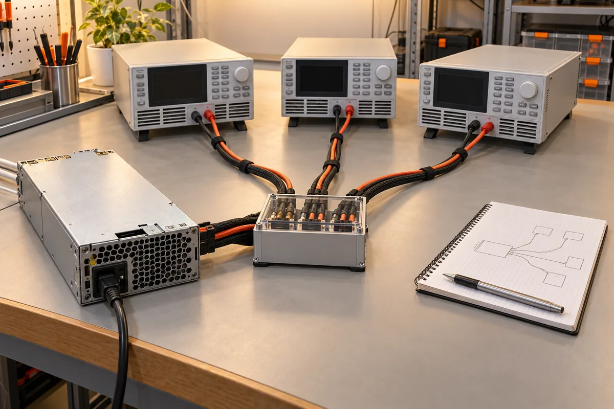
Compare the host table with manufacturer-approved rail and combined-load limits for the exact assembly. The illustration shows a general distribution principle, not the internal circuitry or verified capacity of G1392. Separate branches can share upstream resources, so branch labels alone cannot establish simultaneous availability.
Ask whether limits change with module population, airflow, ambient temperature, or input condition. If a document provides only individual outputs, request the missing load-combination rules. An incomplete table is a documentation gap, not permission to assume unrestricted operation.
Validate connectors, harnesses, and thermal performance together
Electrical compatibility requires more than matching voltage labels. Obtain a controlled connector drawing and pin assignment for the board, each approved PSU, and the host harness. Confirm connector manufacturer and part number, keying, polarity, return paths, contact population, and any control or sensing connections. Do not derive a pinout from photographs or a visually similar product.
Current capability must be evaluated across the complete path. Relevant details include contact ratings under the specified conditions, cable gauge and length, termination quality, board or busbar construction, and permissible temperature rise. Where multiple contacts share a load, obtain the manufacturer’s allocation rules rather than assuming perfect current division.
Thermal approval must reflect the installed chassis. Fan direction, restrictions near the PDB, cable routing, adjacent heat sources, and a changed airflow pattern after module loss can affect operation. Request cooling requirements and derating information for the approved assembly, then plan qualification against the host’s real operating scenarios.
Any validation plan should define measurement locations, operating conditions, and pass/fail criteria from controlled requirements. No test results are established here. Work involving energized assemblies, fault simulation, or connector temperature measurements should follow the manufacturer’s procedures and be performed by qualified personnel.
Resolve mechanical dimensions and approved module pairing
The manufacturer-confirmed 185 mm CRPS pairing statement and the seller’s unverified 265 × 77 × 84 mm dimension claim must not be substituted for one another. They may describe different objects, but an annotated drawing is needed to establish that relationship. The catalog dimensions are not a reliable fit specification.
Request drawings for both the PDB assembly and the approved removable modules. They should identify mounting holes, insertion datums, connector locations, engagement requirements, retention features, and service clearances. Confirm whether carriers, handles, fasteners, and cable exits are included in the envelope. A 2U designation alone does not prove clearance within a particular server.
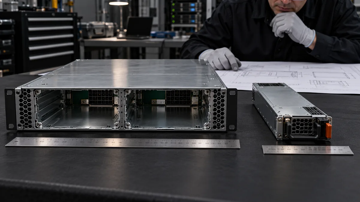
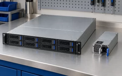
Check the insertion and extraction path as well as the installed position. Interference with a fan wall, rear cabling, chassis retention feature, or output harness can defeat an otherwise plausible dimensional match. The illustration distinguishes assembly and module boundaries; it is not a dimensioned drawing of the offered item.
Request approved PSU part numbers and revisions, including any permitted mixed-module combinations. Matching length and power description is insufficient: connector arrangement, control behavior, output characteristics, firmware, and airflow may differ. Obtain written pairing approval rather than treating all 185 mm CRPS modules as interchangeable.
Clarify the input interface and request a complete purchase package
The unverified Powernexu 90–264 V field does not establish the PDB’s input voltage or the assembly’s accepted mains range. Ask the supplier to identify the relevant interface and provide the approved PSU input specification. Where applicable, obtain input-dependent output capacity and facility-power requirements; an accepted voltage range alone does not establish full-load capability throughout that range.
Before releasing the order, request a revision-controlled package containing:
- Manufacturer part numbers, board revision, label photographs, and a clear relationship to the seller’s identifier.
- A bill of materials defining the PDB, carrier, PSU modules, harnesses, and included accessories.
- Approved module pairing, mechanical drawings, connector definitions, and host-interface requirements.
- Confirmed rail limits, simultaneous-load rules, normal and surviving-module capacity, and derating conditions.
- Cooling requirements, protection behavior, supported control functions, and authorized service procedures.
- Applicable compliance documentation with a scope that identifies the supplied configuration, plus warranty and substitution controls.
The purchasing decision should rest on that documented configuration. The seller’s suffix and numerical fields are useful search references, but they cannot establish capacity, redundancy, electrical compatibility, or chassis fit without exact-configuration evidence.