Replacing a server power supply means removing the identified failed module, installing an approved replacement, and confirming that the host recognizes a healthy power path again. Whether the server can remain running is a separate question: the exact platform procedure, installed configuration, surviving supply, and available input determine that permission. A removable handle does not establish it.
This procedure focuses on executing an already justified replacement, rather than choosing a spare or adding redundancy to a single-supply server. It uses an AC-powered Lenovo ThinkSystem SR645 as a bounded service example. Apply your own server’s service manual at the rack; another chassis may have different release hardware, input connections, operating restrictions, and recognition behavior.
Decide whether this replacement requires a shutdown
Before touching a cord, identify the full server model and retrieve its removal and installation instructions together. Read their prerequisites, safety notices, and completion steps. A document covering a similar generation is a useful search lead, not permission to perform the same operation. In particular, distinguish a rear-removable PSU module from a fixed internal supply with output harnesses. The latter requires a different access and isolation procedure.
Lenovo’s ThinkSystem SR645 removal instructions explicitly require shutdown when the supply being removed is the only installed unit. They also specify shutdown for its 240 V DC supply procedure. The AC example here therefore does not authorize servicing DC terminals or keeping a single-supply host online.
For a potentially eligible live replacement, confirm that the remaining module and its energized feed are healthy and can support the configured workload under the OEM’s conditions. Two populated bays alone do not establish available redundancy. A disconnected partner, unsupported combination, or configuration requiring both outputs changes the service risk. Resolve an unknown surviving-path state before removing hardware; move the workload or plan an orderly shutdown when the required service conditions cannot be established.
Agree on the operational boundary before starting. Identify who can stop the change if the server reports a new power fault, and what happens to applications if shutdown becomes necessary. Schedule recovery work so storage activity, backups, and user sessions are handled deliberately. The desire to avoid downtime does not enlarge a supply’s supported operating envelope.
Match the fault record to the physical bay and cord
At a crowded rack, correct identification is part of the repair. Record the server asset or service identifier, rack position, reported PSU bay, relevant event timestamp, and the actual fault description. Then compare the management record with the rear-panel bay markings and the documented indicator meanings. Do not translate an ambiguous dashboard label into “left supply” from memory: the viewing direction and platform numbering can differ.
Trace the target module’s input cord to its assigned source without disturbing the healthy path. Verify the outlet or PDU designation against the site’s cable record. If the cords cross behind a cable management arm, resolve the crossing visually before unplugging anything. Where site procedures use a second-person check, have the second person verify the server, bay, and intended cord together, rather than merely agreeing that one indicator looks abnormal.
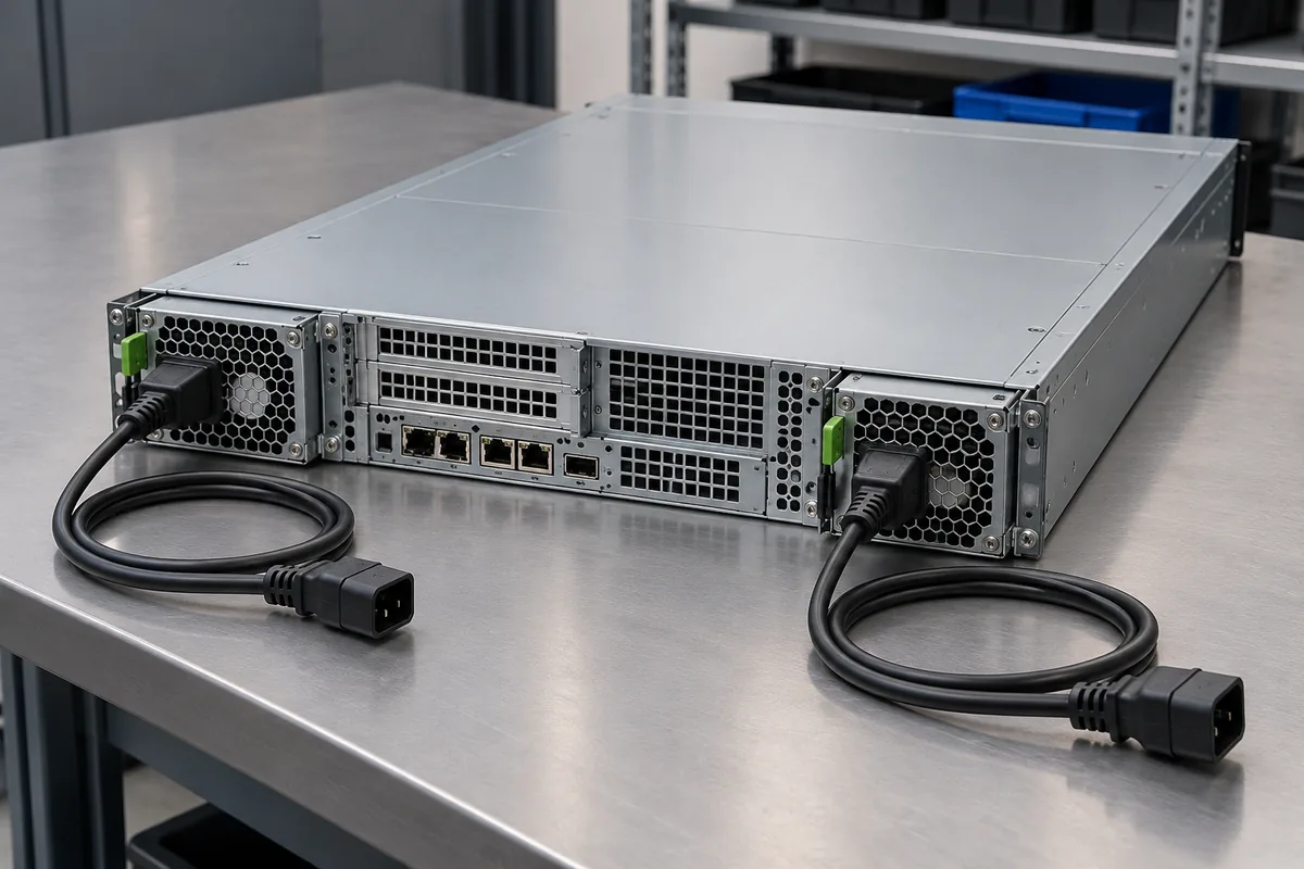
Preserve the current event log and a view of the installed supplies before the change. This is a baseline for distinguishing the original fault from the expected input-loss or removal events created during service. It also prevents a later reader from assuming that every warning in the window represents a second failure.
A missing input is not automatically a failed converter. If the work order has not established why replacement is indicated, resolve that diagnosis first. An interrupted upstream source can leave a perfectly serviceable module without power. The separate discussion of PSU failure and firmware state addresses that diagnostic territory; the execution sequence below assumes the replacement decision is already supported.
Prepare the spare and extraction path before disconnecting
Place the approved replacement where it can be reached without setting it on another device or blocking a walkway. Compare its service identity with the work order before removing the installed unit. Keep its packaging for handling and any required return. Detailed procurement checks belong earlier in the process; discovering an unapproved substitute while a production bay is empty is avoidable.
Inspect the new module’s enclosure, guide surfaces, connector area, handle, and latch for visible damage. Do not straighten contacts or modify a key to make a spare fit. A damaged or inconsistent part is a reason to pause and obtain a supported replacement. Use the OEM’s electrostatic-discharge precautions and handling surfaces, and keep fingers and tools away from the mating contacts.
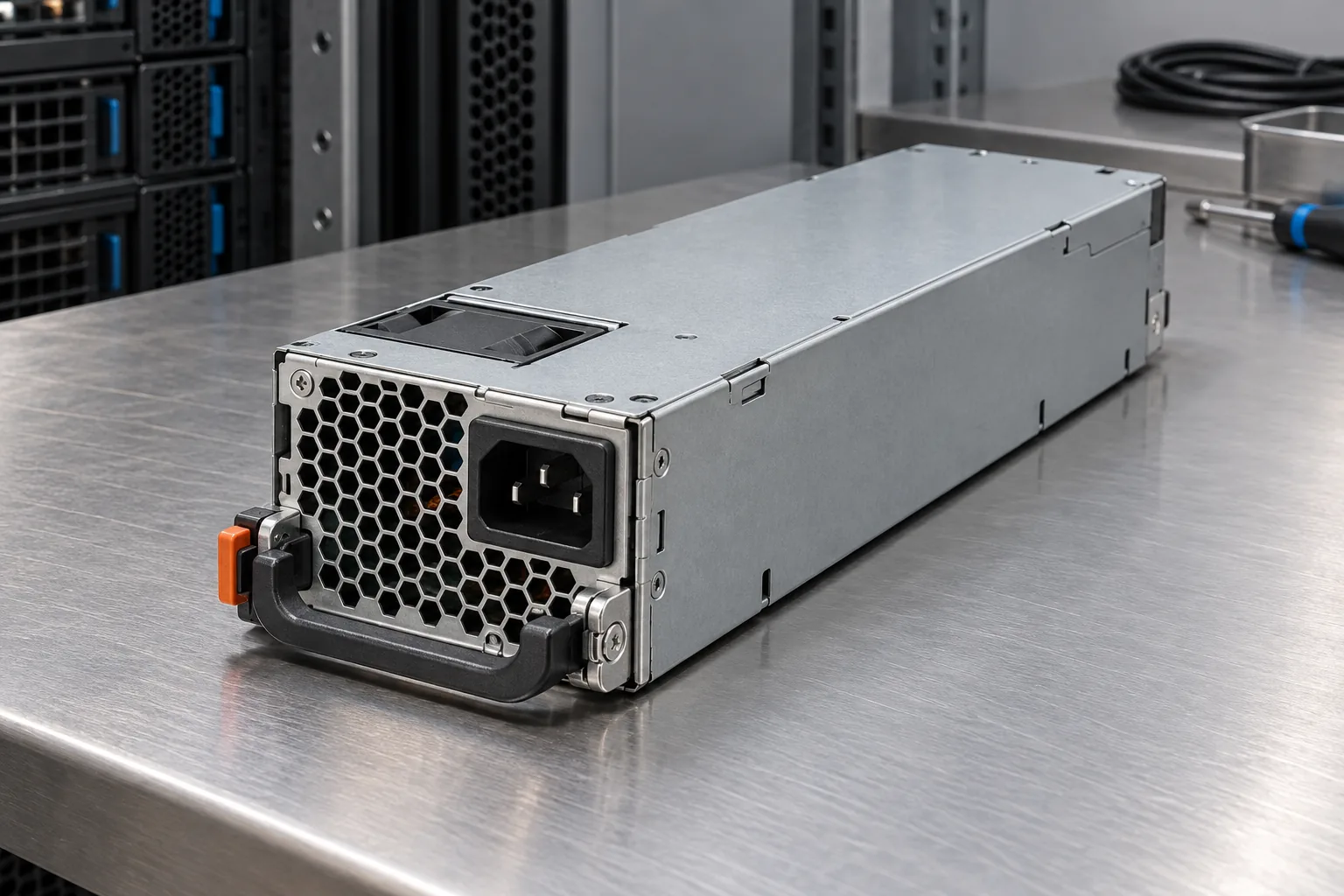
Check the full withdrawal distance. A closed rear door, bundled cable, or cable management arm may let the handle move while preventing the body from clearing the bay. Arrange access according to the rack and chassis instructions before disconnecting the target. Support cables so moving the arm does not pull on the surviving PSU, network ports, or storage connections.
Also identify the stop point if installation cannot proceed. Have the documented bay filler available where the manufacturer requires one for normal operation with an empty position. A failed latch or obstructed connector should not turn into an extended attempt with the cooling opening left unaddressed. Do not improvise an acceptable empty-bay duration; use the platform’s stated restrictions and service plan.
Remove the identified module using the documented release
The following sequence describes the AC-module actions in the SR645 documentation, not a universal latch direction. Lenovo requires both PSU bays to be occupied by supplies or the permitted supply-and-filler arrangement during normal operation. Its removal procedure also addresses rack cable-management access.
- Complete the shutdown when required, or establish the approved live-service conditions before proceeding.
- For the target AC module, disconnect the power cord from the supply and the electrical outlet.
- Press the release tab toward the handle and carefully pull the handle to slide the module out of the chassis.
- Install the replacement, or the specified filler if the bay will otherwise remain empty.
Throughout the withdrawal, keep the removed unit controlled and clear of neighboring cords. Stop if it binds unexpectedly. The problem might be an incompletely released latch, an obstruction, or damage; additional force does not establish which one. Do not insert a tool into the bay to clear an unseen obstruction while the system remains energized. Follow the vendor’s escalation and isolation procedure.
After removal, place the suspect module in its designated protective packaging or on the approved handling surface. Keep its bay association attached to the service record. When several servers are serviced together, a loose failed module can easily become confused with a verified spare. Labeling its status immediately prevents a later technician from returning it to stock accidentally.
Seat the replacement before restoring its input
For the SR645 installation, Lenovo directs handling on a static-protective surface, insertion until the new module snaps into position, and AC connection to a properly grounded outlet. Restore the cable management arm if moved. If the server was off, turn it on; Lenovo calls for both the PSU input and output LEDs to be lit as the operating check.
Apply insertion force through the documented handling points. Do not use the power cord to pull the module into alignment. If the housing stops short, remove pressure and check the part, guide alignment, and service instructions. A latch that has not engaged is not made acceptable by an indicator lighting or a management inventory entry appearing.
Restore the target cord to the intended source and any specified retention arrangement. Check that the cable has sufficient slack for the approved rack movement and does not lie across the module exhaust or interfere with its neighbor’s release. Return movable accessories to their service position without pinching the cord. Make this physical inspection before walking away from the rear of the rack.
The replacement can now be present mechanically while recognition is still incomplete. Allow the host’s documented discovery or initialization process to finish before interpreting the management result. Do not borrow a waiting time from a different model or repeatedly reseat the supply to accelerate detection. If the OEM describes a firmware-related replacement action, follow that procedure rather than starting an unplanned update during physical service.
Read back the repair and respond to what remains
For a host serviced while shut down, include the normal startup in the repair observation. Watch for power-related events during boot and when the intended applications return. A spare that is recognized with the server idle has not yet been observed through that transition. For a host kept online, compare the application state before and after the change and preserve any interruption report. These observations support the service record without requiring an improvised cord-pull test. If the change plan calls for a separate redundancy exercise, execute it under its own approved conditions after the normal state has recovered.
Reopen the management interface and confirm a fresh reading, rather than relying on a screen left open before removal. Check the replaced bay’s presence, reported identity where available, input condition, output state, and active faults. Compare those observations with the local indicators defined for the server. A running operating system shows continuity of service; it does not prove that the new module is contributing power.
Next distinguish restored module health from restored system redundancy. The host may recognize the replacement while retaining a mismatch, insufficient-capacity, or unavailable-partner condition. Confirm the intended redundancy state against the actual server configuration. Avoid treating equal output readings as an acceptance requirement: workload distribution and standby behavior are platform dependent. Use the OEM’s status definitions instead of expecting a particular numerical split.
If the new supply is absent from inventory, verify the physical seating and the reported bay before considering a supported reseating procedure. If input remains unavailable, examine the assigned source and cord through the approved site process. If input is present but output or recognition remains faulty, preserve the new events and escalate with both module identities and the bay history. Do not start exchanging modules between production bays without an OEM-supported diagnostic plan.
Compare timestamps around disconnection, removal, insertion, and restoration. A historical “PSU removed” event may remain in the log after the condition clears. Conversely, acknowledging a warning does not repair an active fault. Record the final current state and any unresolved condition separately from the historical service events, so monitoring and the next shift receive an accurate handover.
A second replacement is a separate service decision. For the SR645, Lenovo says to replace two supplies one at a time and not disconnect the second until the first replacement’s output LED is lit. Beyond that explicit prerequisite, reestablish the approved remaining-path conditions before another removal. If the first replacement has not recovered, the second module is not available for routine live withdrawal.
Close the work order with the removed and installed serial numbers, target bay, source outlet, service timestamps, and final observed state. Mark the removed unit for return or investigation according to its disposition instructions. Leave the server with access hardware restored and a clear record of whether redundancy actually returned. That record is what lets the next operator distinguish a completed replacement from a server that merely stayed online through the work.