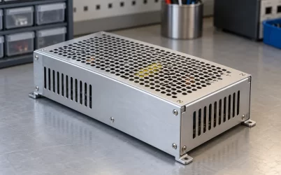
An industrial electronics power supply can meet its published ripple specification while a nearby sensor or data converter still produces unstable readings. The two observations are not contradictory. The datasheet value belongs to a defined test point, bandwidth, load, and measurement connection; the installed sensor sees the supply through cables, returns, local regulators, and its own signal chain. Before specifying a quieter converter, separate noise generated at the source from disturbance added along the distribution path and sensitivity inside the electronics. Those are three different engineering problems, even when they appear as one noisy process value.
A fluctuating reading is also not proof of excessive power-supply ripple. Mechanical variation, sensor self-noise, an unstable reference, electromagnetic pickup on the signal cable, or software sampling can create the same symptom. Conversely, a good average DC voltage at the supply terminals does not establish that a fast disturbance is absent at the remote device. The useful comparison is between the manufacturer’s defined output test and the actual voltage and signal behavior at the point where the measurement is made.
The ripple number belongs to a measurement circuit
Published ripple and noise are usually expressed as a peak-to-peak or RMS value over a stated frequency range and under specified operating conditions. Those details are part of the result, not footnotes. The displayed amplitude can change when a scope bandwidth limit changes, when its ground connection forms a large pickup loop, or when the probe is moved from the converter output to the end of a long cable. A comparison between two supplies is meaningful only after their measurement conventions are understood. A smaller number obtained under a narrower bandwidth is not automatically a cleaner rail for the sensor’s relevant frequency range.
A concrete manufacturer example shows why the fixture matters. TDK-Lambda’s NV300 application note defines its ripple/noise observation over 10Hz to 20MHz, with a 20MHz oscilloscope bandwidth, a 150mm twisted-pair output connection, specified capacitors at the measurement point, and a short probe earth. These are conditions for that particular published test, not universal instructions for every industrial supply. If a field measurement uses several meters of machine wiring and a long probe ground lead, it is observing another electrical arrangement. It should not be pronounced a datasheet failure merely because the trace is larger.
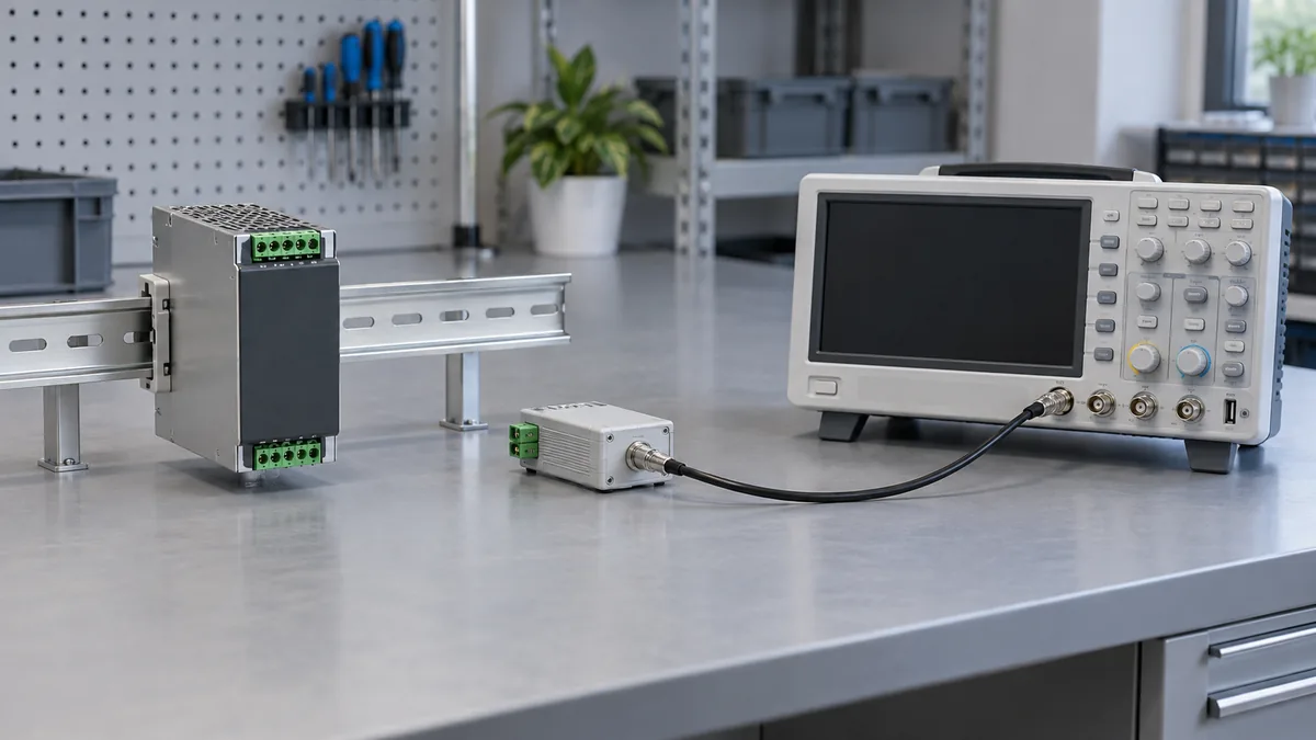
The scope connection can become part of the apparent noise. A long ground clip and probe tip enclose area that picks up nearby switching fields. A converter may then seem to have sharp spikes that are partly in the measuring loop. Shortening the measurement loop or using a connection method appropriate to the specified circuit can change the trace without changing the source. This does not mean every sharp spike is an artifact. It means an unqualified screenshot cannot establish whether the noise originated inside the PSU, on the distribution conductors, or in the probe arrangement. Work on energized equipment requires qualified personnel and suitable instruments; a grounded bench oscilloscope is not automatically safe on every circuit.
Load condition matters as well. Some supplies change switching mode at light load; others encounter their worst low-frequency ripple under a particular line or load condition. A sensor drawing a small amount of current from a larger 24V cabinet rail may experience a very different source operating point from a nameplate or full-load test. The exact behavior belongs to the converter model. The engineer needs the relevant load, input, temperature, and test setup before treating a catalog ripple value as a prediction for the installed machine.
Between the converter and the sensor, the cable becomes electrical hardware
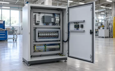
Voltage at the supply terminals is not identical to voltage at the device. A cable has resistance and inductance; terminals and connectors contribute impedance; the return conductor carries current too. A changing current from a neighboring load can create a local voltage change on any segment shared with the sensor. The converter may still regulate correctly at its own output while the sensor’s local supply or reference moves. This mechanism is especially easy to miss when a wiring drawing represents the entire 24V network as one continuous line.
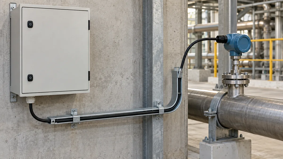
There are two distinct kinds of disturbance to avoid conflating. A slow or stepwise drop caused by current through cable resistance is a distribution-voltage problem. High-frequency energy can couple from fast switching edges through shared impedance or electromagnetic fields. Increasing the converter’s voltage setting to compensate for a remote DC drop will not necessarily reduce that high-frequency coupling, and it may overvoltage closer loads at light current. Conversely, adding a high-frequency filter may leave a substantial DC cable drop unchanged. Diagnose the frequency and location before choosing a remedy.
The return path deserves the same attention as the positive feed. If a sensor and a high-current output module share a length of return conductor, the sensor’s local “zero” can move with that other load’s current. The analog input may then report a change although the physical quantity being measured has not changed. Differential measurement, suitable isolation, or a different distribution layout can reduce this effect in a compatible system, but none should be prescribed without the actual sensor and input-module specifications. A shield connection is not a substitute for a correctly rated power return.
The location of a capacitor or filter also changes what it can achieve. A capacitor close to the converter output can lower one component of source ripple, while a suitable local filter near the sensitive electronics can address voltage reaching that load after cable pickup or shared-impedance disturbance. Cable length and branch layout affect the impedance between those two places. More capacitance is not automatically better: it can increase startup demand, interact with source current limiting, and alter transient response. The supply’s allowed external capacitance and the device’s input characteristics constrain any added network.
The sensor’s reading is not a direct voltmeter on its supply rail
A sensor measurement travels through a signal chain. The transducer, excitation source, amplifier, filter, voltage reference, analog-to-digital converter, clock, and digital processing can each shape the result. Noise at a supply pin may be rejected to some degree by one stage and coupled strongly through another. Power-supply rejection is frequency dependent and product specific; a single DC accuracy figure cannot describe it. A switching component at a frequency relevant to the sampling system can appear in the digitized result, while a much larger disturbance outside the signal bandwidth might have little visible effect.
Consider a pressure transmitter whose sensor element is stable while the controller reports a periodic ripple in the process variable. The ripple might already be present on the sensor’s excitation rail. It might instead enter the analog input through a shared return, the signal cable, the ADC reference, or sampling interaction. Replacing the upstream industrial PSU with a lower catalog ripple figure addresses only the first possibility directly. Even then, its benefit depends on how the local regulator and signal chain respond at the relevant frequencies. The example identifies possible paths; it is not a claim about any particular transmitter or Powernexu device.
A separate local regulator can improve a sensitive analog rail when its dropout, rejection across the problem frequency, load current, and thermal loss are suitable. A low-dropout linear regulator, for example, does not magically erase every switching spike; its rejection changes with frequency and with headroom. A local switching stage may be efficient but introduce its own spectral content. The choice follows the analog device’s requirements and the measured disturbance. It is often more useful to keep a robust cabinet-level supply for bulk power and treat the precision rail locally than to demand that one distant source directly satisfy every ADC pin’s noise condition.
The voltage reference may be even more consequential than the bulk rail. If an ADC compares a sensor signal to a reference that moves, the digital code can move although the sensor signal is stable. In other architectures, the excitation and reference may move together, changing how much supply variation appears in the result. Neither behavior can be inferred from “24V industrial sensor” as a category. The actual input topology and reference arrangement determine whether source ripple, ground movement, or reference noise dominates. This is why a sensor datasheet and controller-input document are as relevant as the PSU datasheet.
Read the waveform by where it first appears
A useful technical explanation of a noisy reading needs synchronized context, not a ritual checklist. If the same frequency component is visible at the converter’s specified output test point and at the sensor supply, the source is a plausible contributor. If it appears mainly after a long branch or when another machine load operates, the distribution path deserves closer attention. If the local sensor supply is quiet by the relevant criterion while the analog input or ADC output is noisy, the signal chain remains in question. These comparisons do not establish causality from one trace alone; they locate the boundary where the behavior changes.
Time and frequency views answer different questions. A brief voltage sag during a machine event is easier to interpret in a time record. Repeating narrowband interference may be easier to recognize in a spectrum, provided the instrument and sampling setup do not invent a spur. Random noise, periodic switching ripple, and a low-frequency load-induced drop should not be collapsed into one peak-to-peak number. The sensor may respond to only part of that spectrum. The definition of acceptable noise therefore comes from both the supply’s specified output measurement and the end electronics’ permitted error or performance, each at its own location.
It is tempting to cite a universal millivolt ripple target for industrial sensors. That would be misleading. Different sensors and ADCs use different local rails, references, filtering, signal amplitudes, bandwidths, and rejection. The exact supply may publish a ripple/noise limit under a particular fixture; the sensor may publish accuracy or input-supply requirements under another set of conditions. A defensible system target translates the application’s allowed measurement error into the relevant internal rail or reference disturbance. Without that translation, a lower catalog ripple number is an attractive but unproven procurement preference.
When a filter helps, it belongs to a defined path
A filter can attenuate a known frequency component between the source and a sensitive load. It also introduces impedance and sometimes loss. If the sensor current changes, that impedance can create a voltage drop or transient of its own. An LC network can interact with a regulator control loop or with the input capacitance of a downstream device. A ferrite bead is frequency dependent and can saturate under DC current. These are reasons to define the disturbance and load before adding parts, not reasons to avoid filtering altogether.
Physical routing may be as effective as an electrical component when the problem is pickup rather than generated ripple. Separating low-level signal wiring from high-current switching conductors, managing return paths, and using the shielding or cable type specified for the sensor can reduce coupling. The effect depends on the actual installation geometry and equipment grounding scheme. A neat cabinet is not necessarily a quiet one if unrelated circuits share a high-impedance reference segment. Equally, a very low-noise supply cannot prevent interference entering downstream of its terminals.
The installation can therefore pass a PSU datasheet test and still need a better sensor power and signal arrangement. Treat the published ripple value as a qualified property of the converter. Treat the installed sensor reading as the outcome of the whole path from source to local rail, reference, signal input, and conversion. Once the first point where unwanted variation appears is known, the remedy becomes specific: a source with different measured output behavior, a corrected distribution path, or a local analog-stage change. None is an automatic substitute for the others.