The CRPS3500CL5M is a 3,500 W, 54 V server power module with a 265 × 73.5 × 40 mm enclosure. That 265 mm length is the first practical distinction to resolve: a bay built around a 185 mm CRPS module cannot be assumed to accept it, even if the face width and height look familiar. Great Wall Power lists four 54 V output-current figures but leaves the input-voltage field empty. Consequently, the public listing identifies the module and its maximum published output; it does not establish which AC or DC feed produces each current rating. This article separates those known facts from the chassis and electrical questions that require a revision-specific manufacturer drawing.
Read the CL5M identity before interpreting the 3,500 W label
The CRPS3500CL5M product record identifies a Platinum-class module with a +54 V main output, a +12 V standby output rated at 2 A, forward airflow, and a stated operating range of 0–55°C. Its dimensions are 265 mm long, 73.5 mm wide, and 40 mm high. Great Wall Power’s manufacturer specification page reports the same major values. These are model-specific published facts, not a statement that any 54 V CRPS shelf can use the module.
The manufacturer lists main-output currents of 24.1 A, 48.2 A, 53.8 A, and 64.82 A. At a nominal 54 V, those represent about 1.30, 2.60, 2.91, and 3.50 kW respectively. Multiplication explains why the largest listed current aligns with the 3,500 W headline. It does not explain the operating conditions behind the other three entries. They might correspond to input bands or another rating condition, but the public page does not say. Assigning an AC voltage or DC feed to one of them would turn an inference into a false specification.
Nor should “Platinum” be converted into a single efficiency percentage for a thermal budget. The listing states a class, while losses in a specific server depend on the certified test conditions and actual operating point. The page also names CQC and 80 PLUS; it does not provide a complete per-market approval matrix for the ordered revision. Procurement documents should carry the exact certificates required for the destination system rather than extrapolating from a short catalog field.
The extra 80 mm occupies real chassis volume
A useful comparison is the CRPS3200TS5, another 54 V module listed at 185 × 73.5 × 40 mm. The CL5M keeps the same published width and height but extends 80 mm farther along the insertion axis. That is roughly 43% more body length than the 185 mm unit. The arithmetic is simple; the system consequence is not. A rear-access server can have enough external rack depth yet still have a power cage, fan wall, cable route, or motherboard keep-out that limits the PSU bay to a shorter module.
Measure from the module seating datum, not merely from the rear panel to an empty point inside the chassis. The insertion path needs space for the full body, connector engagement, latch travel, and any guide rails or polarization features. At the inboard end, verify clearance to a fan wall, PDB, cable bend, bracket, and serviceable components. At the exterior, check that the extraction handle and power cord remain accessible with the server installed in its rack. None of these relationships is established by a common 73.5 × 40 mm cross section.
An engineering drawing also has to settle whether the 265 mm figure includes every projecting feature relevant to the host. Published envelope values are useful for early layout, but a mechanical interchange claim requires the controlled drawing of the PSU and the host bay. Rail position, latch location, blind-mate depth, insertion stops, and connector mating sequence can differ between long and short bodies. An 80 mm gap in nominal length is enough to make a blind trial insertion a poor way to discover the difference.
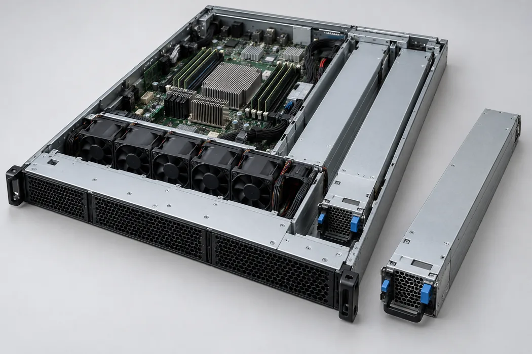
Longer does not automatically mean a different rack unit height. The published 40 mm height fits within a low-profile module class, but chassis fit depends on where that height is measured and what surrounds the module. A dense accelerator server may spend the additional depth on cooling hardware or routing while leaving little spare space for a longer power cage. The physical packaging decision therefore belongs near the start of platform design, before PDB placement and fan-wall tooling become fixed.
A 54 V source changes the downstream power path
The +54 V rail should be treated as a system distribution voltage, not as a direct replacement for a +12 V CPU or GPU rail. A platform designed for 54 V delivery typically routes that bus through a suitable distribution assembly and converts it locally to the voltages required by processors, memory, fans, and control electronics. Which converters are present, how they are sequenced, and what input range they accept are properties of the host design. The 12 V standby output is a separate auxiliary rail and cannot be interpreted as a 3,500 W 12 V capability.
At 3,500 W on an idealized 54 V bus, current is approximately 64.8 A, matching the manufacturer’s largest listed figure after rounding. The current is large enough that contact resistance, bus-bar geometry, copper loss, and connector heating matter. For example, a total series resistance of 2 milliohms would dissipate about 8.4 W at 64.8 A, using I²R. That is a hypothetical calculation, not a measured CL5M connector loss. It illustrates why a nominal voltage match says little about the fitness of a real blind-mate interface.
The PDB must be evaluated as an electrical and mechanical assembly. It needs the intended output pins and return paths, adequate current rating, appropriate isolation or ORing behavior for the shelf, and a thermal path that handles connector and trace losses. A photo of a similar CRPS module does not establish these details. The public CL5M listing supplies no connector pinout or PDB part number. Use the released mating-interface document for the ordered hardware revision before treating any existing bay as compatible.
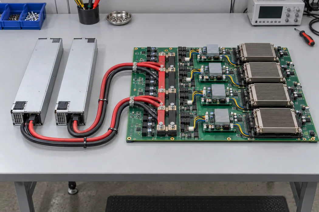
A 54 V bus may be attractive for high-power accelerator systems because it carries a given power with less current than a 12 V bus. For the same 3,500 W idealized load, a 12 V bus would carry about 292 A before conversion losses, versus about 65 A at 54 V. The comparison concerns distribution current; it does not prove that either system has lower total loss without examining conversion stages, conductor sizes, connector design, and operating load. In a server already engineered for a 12 V input PDB, installing a 54 V PSU would be an electrical mismatch even if the module could be made to slide into the enclosure.
The blank input field prevents a full power plan
The most consequential missing value is not subtle: Great Wall Power’s model page leaves “Input Voltage” blank. Powernexu’s supplied model data likewise says the input voltage is unspecified. Other CRPS models in the manufacturer’s catalog publish AC or high-voltage DC input ranges, but borrowing a neighboring model’s range for CL5M is unwarranted. The suffix, enclosure length, and output voltage do not encode a verified facility-feed rating.
Likewise, the four current values cannot responsibly be relabeled as low-line and high-line outputs without a source that maps them. If a rack is supplied through a particular PDU and branch circuit, the available steady output may be lower than the 3,500 W headline under some conditions. The magnitude and boundary of any such derating remain unknown from the public record. Request a rating table that connects each output current to input type, input-voltage range, ambient temperature, and airflow condition. Until then, capacity calculations for a single surviving module should use only a documented operating point.
This matters especially in a redundant shelf. Two installed 3,500 W units do not imply 7,000 W of protected load. If one module must sustain the server after the other fails, the surviving module’s permitted output at the actual feed and temperature sets the relevant ceiling. If that ceiling is one of the lower current tiers, the difference could be substantial. The public figures indicate multiple capacity points but do not tell us which applies to a planned data-center feed. A site-specific electrical design therefore cannot close on the catalog headline alone.
Input information is also needed upstream. The PDU, cord, receptacle, protective device, and branch circuit must cover the supply’s actual input characteristics. Without the manufacturer’s approved feed range and input-current data, an engineer cannot accurately size those elements from a 3,500 W DC output rating. Dividing output power by an assumed voltage and efficiency may offer a rough thought experiment, but it is not an equipment rating. Keep facility design tied to the exact input label and controlled electrical specification.
Forward airflow has to agree with the shelf
The CL5M listing marks “FR” for forward airflow and gives a 0–55°C operating range. Those entries do not describe a guaranteed output at every ambient or under every shelf pressure condition. The meaning of the airflow designation should be reconciled with the manufacturer’s drawing and the host’s inlet-to-exhaust path. In a dense server, the power cage may draw from a shared plenum or discharge near an accelerator fan wall; reversing the expected flow can create recirculation or leave the PSU without sufficient cooling.
The longer body changes where heat is released within the chassis and how much of the module sits alongside adjacent parts. It can also change the obstruction presented to a common fan path. A thermal model should use the final cage geometry and measured inlet temperature at the PSU, rather than room temperature alone. Check the region near the blind-mate connector and the neighboring cable bundle as well as the exhaust face. Platinum classification helps describe tested conversion performance, but it does not specify the loss distribution inside this particular assembly.
For service access, the airflow arrangement should still allow a technician to remove a module without disturbing unrelated power and cooling paths. If a server depends on several PSU positions for redundancy, the remaining modules must retain adequate inlet air while one position is empty or being serviced. The exact behavior depends on the server’s baffles and fan control, so it cannot be read from the module catalog. Mechanical drawings and a representative host test are the appropriate evidence.
What can be decided from the public record
The CRPS3500CL5M can be shortlisted for a new 54 V server shelf that has room for a 265 mm module. Its published 3,500 W maximum, 54 V main rail, 2 A 12 V standby rail, forward-airflow designation, and Platinum class make its intended role clear. A host constrained to a 185 mm bay or built around a 12 V distribution board is outside that straightforward shortlist. The same nominal CRPS family name does not overcome either mismatch.
Before ordering it as a drop-in spare, the unresolved documents are concrete: the revision-controlled mechanical and mating-interface drawings, the input-voltage and output-derating table, the standby and control interface, and the applicable approval evidence. Those are not generic formalities; each closes a gap visible in the published record. A purchase description that includes the exact model suffix and hardware revision helps prevent a visually similar but electrically different module from entering the spares pool.
For a clean-sheet server, the long body can be accommodated deliberately: reserve the full insertion corridor, design the 54 V PDB and local conversion path, and coordinate the PSU airflow with the enclosure fans. For an existing server, the answer is narrower. The manufacturer listing supports identification and preliminary layout, but it does not establish interchangeability or full-load operation on a specified feed. The decisive next artifact is the CL5M’s controlled interface and rating documentation for the exact unit being sourced.