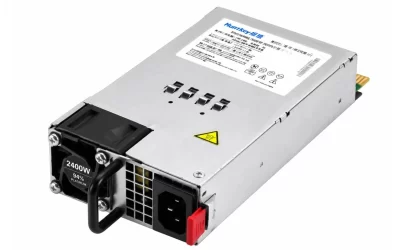
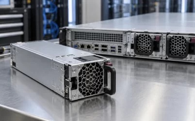
The G1232-1600WNA is a 1,600 W low-voltage DC input server power supply, not an AC mains module or a power distribution board. Gospower identifies this exact model in its LVDC selection chart as a 1,600 W, −48 Vdc input unit in a 185 mm body, with a Gold efficiency classification. Its LVDC family page describes a 185 × 73.5 × 40 mm format, 12 Vdc output, and 55°C maximum operating temperature; those family statements do not establish every revision-specific operating limit. Powernexu additionally lists a 36–72 V DC input range and 133.33 A maximum output current, but those two figures need confirmation against the ordered revision’s controlled manufacturer specification. The useful question is how much power this particular revision can deliver while a nominal 48 V battery bus moves through its operating range. Neither the broad input window nor the 1,600 W nameplate alone answers that question. Obtain the manufacturer’s input-dependent output and thermal limits before assigning a protected server load.
G1232 belongs on the DC side of the power architecture
In a battery-backed telecom or distributed server installation, a DC plant may present a nominal 48 V supply rather than utility AC at the equipment bay. The G1232-1600WNA converts that low-voltage DC input to a 12 V server output. It therefore occupies a different position from an AC-input CRPS, even when the external module dimensions look familiar. It also differs from a PDB: a distribution board combines and routes the outputs of installed modules, while this unit performs the DC-to-DC conversion. A distribution board and a DC-input converter have different jobs, so a similar wattage designation cannot establish interchangeability.
The Powernexu G1232-1600WNA product page gives the model’s catalog identity and its listed electrical and mechanical figures. The Gospower LVDC family page independently identifies G1232-1600WNA as a member of a low-voltage DC, battery-input server PSU series and describes a 185 × 73.5 × 40 mm format with 12 V DC output. These two sources support the product category. They do not provide a controlled, suffix-specific input-current curve, connector drawing, or full-power voltage threshold in the accessible text. Those absences matter when a DC plant can spend meaningful time below its nominal voltage.
The suffix should remain intact in purchasing records. A G1232 family photograph or a G1232-0800WNA listing can establish a family resemblance, but cannot define the 1,600 W unit’s operating envelope. Likewise, an AC-input module with the same 185 mm body might enter a superficially similar bay yet require an entirely different source. The installed input wiring and the host’s approved module list must identify the actual revision before any substitution is proposed.
The battery window is an input range, not a flat output curve
Powernexu publishes 36 V as the minimum input and 72 V as the maximum for G1232-1600WNA. Those numbers describe a catalog input window. The page does not state that 1,600 W is continuously available at every point within it. As the DC bus falls, a converter supplying the same output power must draw more input current, allowing for conversion losses. This raises the demands on the feed conductors, contacts, fusing, and input stage precisely when a battery system is discharging.
For scale, 1,600 W of output at an illustrative 90% conversion efficiency would require approximately 1,778 W of input. That would mean about 37 A at 48 V, roughly 49 A at 36 V, and about 25 A at 72 V. The 90% figure is an assumed example, not a measured G1232 efficiency or a supplier guarantee. The calculation shows the direction and size of the current change; actual current also depends on the model’s efficiency at each operating point and on any low-voltage derating. A protection device or cable sized from the nominal 48 V case alone could therefore be underspecified.

Some reseller tables for this suffix show a lower current figure in parentheses and a boundary around the lower part of the input range, but their notation is inconsistent and one version even labels a DC interval as AC. Those entries are useful as a prompt to ask for a controlled manufacturer curve, not as a dependable derating schedule. Powernexu’s own page does not map its 133.33 A output-current entry to a particular input voltage. An equipment specification should keep the two claims separate: the catalog lists a 36–72 V input window and a 1,600 W class output, while full-load operation at the lowest input remains to be confirmed for the ordered revision.
At the site level, “48 V” is a system name rather than a promise that every terminal sits at exactly 48 V. Rectifier set point, battery state, cable drop, protection devices, and transients affect the voltage actually seen by the module input. A plant specification should therefore describe the voltage at the module terminals under both normal operation and the lowest permitted battery condition. It should also account for what happens during source transfer, recharge, and recovery from a brief sag. An input range printed on a product page cannot substitute for that operating profile.
Where the DC plant ends and the module begins
The boundary between site infrastructure and server hardware is especially important for a high-current low-voltage input. A designer needs the physical feed and return path, polarity marking, input connector assignment, protective-device coordination, and grounding arrangement for the installed system. The public product listing does not publish an input pinout, so the module must not be wired from a generic connector assumption. Verify the exact drawing supplied for the ordered part and the receiving chassis before energizing it.
Polarity is not a wording detail. Telecom power documents may describe the plant as “-48 V” relative to a grounded return, while a product catalog may give a positive 36–72 V magnitude. Both descriptions can refer to the same potential difference, but they do not identify which connector position is feed, return, or chassis reference. The acceptable grounding and protection scheme belongs to the approved equipment design. Do not translate a voltage magnitude into a connector polarity by convention alone.
At a high load, resistance along the input path becomes visible as both drop and heat. For a purely illustrative 40 A feed, a total series resistance of 20 milliohms would drop 0.8 V and dissipate 32 W across the path. This is not a measured G1232 installation. It explains why the measurement location matters: a cabinet bus reading may appear healthy while the module input is lower after a long cable, breaker, and connector. The source must remain within the approved module envelope at its terminals, including during a one-module-surviving event if the host is redundant.
The 12 V output is delivered through a host interface
Powernexu lists 12 V and a maximum output current of 133.33 A. Multiplying those figures yields approximately 1,600 W, so the numbers are consistent as a nominal catalog point. That arithmetic does not specify output tolerance, peak duration, standby rail, transient response, or what the host may draw after a partner module fails. The 12 V path also includes the module contacts, host PDB, and downstream point-of-load converters. Each can impose a separate current, temperature, or voltage-drop limit.
The 185 × 73.5 × 40 mm envelope helps identify a likely removable-module size class. It does not establish that G1232-1600WNA mates with every bay built for a 185 mm module. Input-side wiring, output blades, guide features, latch geometry, airflow direction, and control pins can differ. This is especially relevant when replacing an AC-input CRPS in an otherwise similar chassis. The DC source has to reach the correct input contacts, and the host PDB has to support the module’s output and signaling. A successful slide-in is a mechanical observation, not electrical approval.
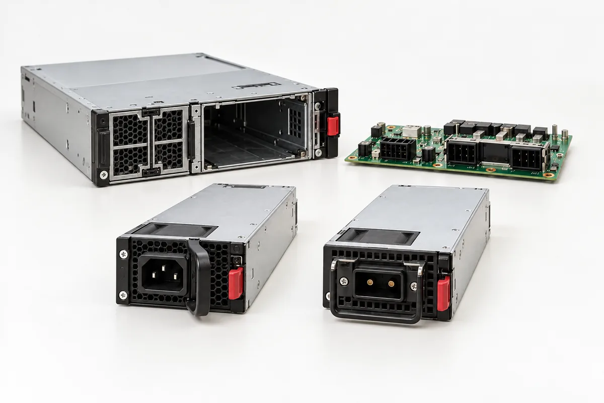
Gospower’s family description mentions 12 V output and the DC battery context, but the accessible page does not provide an exact-suffix mating drawing or a verified PMBus command profile. Reseller descriptions sometimes add standby output, PMBus, current sharing, or internal ORing details. Those features may exist in particular revisions, yet the public evidence here is insufficient to specify pin functions or management behavior for a host integration. Request a controlled interface document rather than copying a reseller feature list into the server bill of materials.
If a system already has an approved G1232 module, compare the proposed spare to the original label and hardware revision. For a new design, compare both sides of the interface: module and PDB drawings, source type, output current capability, present and enable signaling, airflow orientation, and management expectations. This is a focused interface comparison rather than a generic claim that two CRPS devices with the same wattage are interchangeable.
Capacity during a discharged-battery failure case
A 1+1 server architecture normally expects one installed module to carry the protected load after its partner is removed or fails. Whether the G1232-1600WNA can do so depends on the ordered module’s capacity at the voltage actually available during that event. A plant may be on battery when a module fails. If the DC bus is near its lower limit, the surviving unit may face its highest input-current demand at the same moment it assumes the full server load. This combined condition is more revealing than a nominal-voltage bench demonstration.
Consider a hypothetical host that needs 1,200 W from its 12 V bus under a defined workload. One 1,600 W rated module has 400 W of simple nameplate margin, but that is not yet a redundancy conclusion. The margin may shrink if the manufacturer derates output at low input voltage or high inlet temperature, and the host may have transient loads above its sustained figure. Conversely, a well documented lower operating load could fit within a verified derated capacity. The conclusion depends on a voltage-by-load operating envelope, not on adding the ratings of two installed modules.
The output connector and PDB also need to carry the one-module load in the intended redundant state. A supply might be capable of the watts while the host board or a contact is not approved for the resulting sustained current. The same distinction applies to input protection: two parallel modules can split DC plant current in normal operation, but a surviving module’s branch may see a higher load after one is lost. The feed design should match that event rather than only the normal current division.
What the published evidence supports in procurement
The exact model can be described confidently as a 1,600 W class, 12 V output, low-voltage DC input server PSU in a 185 × 73.5 × 40 mm catalog envelope. Powernexu lists hot-pluggable mounting and a 36–72 V input range; Gospower identifies the G1232 family with battery-input server power. That is enough to place the product in a shortlist for a compatible DC-powered server architecture. It is not enough to approve a specific chassis, claim full power at 36 V, or define a live replacement procedure.
For an order intended to support a real site, the decisive documents are the exact-suffix and revision data sheet, input-power or derating curve, connector and mechanical drawing, and the host’s approved-parts record. Ask the supplier to reconcile the 133.33 A catalog current with any manufacturer output-current table and to state the input and ambient conditions behind the 1,600 W rating. If a source uses “-48 V” while another lists 36–72 V, resolve polarity in the connector drawing rather than treating the sign convention as an inconsistency by itself.
A shortlisting record should also preserve what remains unknown. No accessible controlled source in this review proves the exact model’s efficiency curve, 80 PLUS certification, standby-current rating, PMBus implementation, lightning-protection test condition, or low-line full-load threshold. Family-level marketing and third-party descriptions should not silently become exact-revision specifications. Once those gaps are closed, the product’s distinctive fit is clear: a compact DC-to-12 V server module for a host that has a verified low-voltage DC feed, compatible PDB, and an operating load inside the documented input-dependent capacity.