Installing a redundant server power supply starts with identifying what the server already supports. On some systems, a second compatible hot-swap module slides into an empty bay. On others, converting a single-supply server requires shutdown and an OEM cage, power distribution board, or backplane kit. The service manual for the exact server model and configuration determines which job you have. The practical goal is also more specific than seeing two power cords: the server must remain within its supported power limit when one supply or input feed is unavailable, and its management interface must report the intended redundancy state.
Identify the installation path before ordering parts
Record the server model, generation, machine type or service tag, current PSU part number, input type, installed options, and firmware or management version. Check the manufacturer’s parts list and service procedure for that precise configuration. A spare bay visible at the rear is useful evidence, but it does not prove that the internal power hardware, second module, or current chassis configuration supports redundancy. Likewise, the word “hot-swap” on a replacement module describes a capability within a supported system; it does not authorize live conversion of an unprepared chassis.
There are two common paths. A server already fitted with a redundant power subsystem may need only a supported second module, a compatible cord, and a configured source. A single-supply configuration may require a conversion kit that replaces internal hardware. For example, HPE’s ProLiant ML30 Gen10 Flexible Slot redundant-power enablement procedure removes the non-hot-plug supply, installs an RPS cage, connects Flexible Slot backplane cables, and installs supplies in bays 1 and 2. That procedure is specific to the documented ML30 Gen10 configuration; a newer server or another chassis requires its own service instructions.
Classify the job explicitly in the change record: adding a module to an already prepared bay, replacing a failed module in a redundant pair, or converting the chassis. That classification drives the shutdown plan, the parts order, and the acceptance test. If the manual does not identify a supported conversion option, do not improvise one with a second ordinary PSU or a synchronization adapter. The mechanical bay, distribution path, controls, and management behavior must be designed for the server.
Confirm the surviving supply can carry the load
Two installed supplies do not establish useful redundancy if the remaining supply cannot carry the server through a fault. Check the manufacturer’s supported PSU configuration and capacity guidance for the actual processors, memory, storage, accelerators, adapters, fans, and input conditions. Some supply ratings or supported configurations vary with input voltage. Include the planned peak operating state, not only an idle reading. Where an OEM capacity planner exists, use it with the installed configuration and retain its output in the work order.
For a conventional 1+1 arrangement, each active supply must be able to support the required load after its partner or source is lost. Do not simply add the two nameplate wattages and call the sum the redundant capacity. A system with more than two modules may implement a different N+1 or N+N policy; inspect the OEM description and the management console instead of inferring its behavior from module count. Power capping and performance limits may also change the supported operating point. The relevant question is whether the server remains functional at the intended workload after one specified failure.
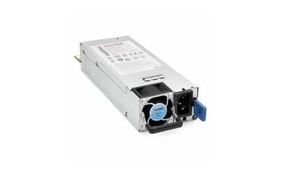
Match the complete supported part number and any required pairing rule. Modules that fit the same opening can differ in generation, connector interface, input type, output rating, airflow, or firmware compatibility. Do not substitute an AC unit for a DC unit or mix models merely because their handles look alike. Confirm the cord connector, wall or PDU receptacle, branch circuit, and available input match the manufacturer’s instructions. If the configuration requires an OEM kit, verify that its cage, board, cable harness, fasteners, fillers, and service instructions are present before scheduling downtime.
Plan safe access and separate power paths
Use the server’s exact service instructions and your site’s electrical and change procedures. For an internal conversion, schedule a controlled shutdown, stop workloads or migrate them, power down, disconnect every supply cord at the source and server, and verify the equipment is de-energized before opening it. HPE’s ML30 Gen10 conversion procedure explicitly calls for removing all power, peripheral cables, the access panel, and internal items needed for access. A serviceable hot-swap bay on a prepared system may permit a module to be added while the server runs, but that permission must come from its OEM guide. Never treat internal conversion work as a live hot-swap task.
Review rack access, cable-management-arm movement, ventilation clearance, module latch orientation, and the location of the bay filler. Preserve the filler until installation, and reinstall one if a supported bay is left empty; openings can affect intended airflow. Keep the replacement module in protective packaging until ready and follow the OEM’s electrostatic-discharge instructions. Do not touch exposed contacts or force a module that does not enter freely. Stop if the latch, keying, or connector differs from the documented part.
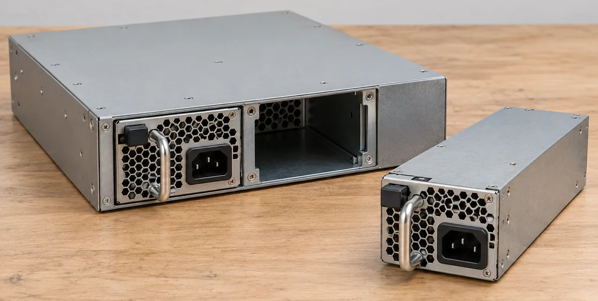
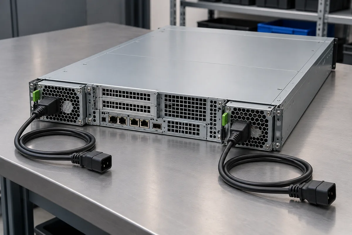
Plan the input topology separately from module installation. If the objective includes resilience to one rack PDU or upstream feed, connect the two inputs to independent, appropriately designed paths rather than adjacent receptacles on the same failed component. Confirm which outlet is on which PDU and which PDU is on which upstream source. Distinct cords alone are not proof of independence. The electrical team should verify branch capacity, protective devices, grounding, and any facility-specific transfer arrangement. Label each cord at both ends so a later service action does not disconnect the wrong feed.
Install a second module in a prepared hot-swap bay
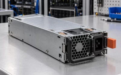
This sequence is for a server whose manufacturer documents adding a second hot-swap unit to an already supported bay. It is a planning outline, not a substitute for the exact service guide. Lenovo’s ThinkSystem SR645 instructions, for example, describe removing a bay filler, sliding the new unit until it snaps into place, connecting it to a grounded outlet, and checking input and output LEDs. Lenovo also says its BMC sets redundancy mode automatically from the installed PSU count. Those details apply to that platform, not to every server.
- Check the server’s current health, PSU inventory, input status, and event log. Resolve an existing supply fault before relying on it to support the server during the work. Confirm that the installed supply has the documented capacity for the current workload.
- Identify the empty bay and its filler. Follow the service guide for access, including any cable-management arm adjustment. Remove the filler only when the supported replacement is ready to install.
- Inspect the new module’s complete label and connector against the approved parts record. Remove protective packaging, align the keyed module with its rails, and slide it into the bay until the latch engages as described by the OEM. Do not use the power cord to pull it into position.
- Connect the approved cord to the module and the planned grounded source in the manufacturer’s specified order. Route and secure it so the latch and cable-management arm remain serviceable without stressing the inlet. Follow the separate OEM procedure for any DC input; polarity and terminal work are not interchangeable with an AC cord installation.
- Observe the module’s documented LEDs and management status, then check that the server reports both supplies healthy and the intended redundancy mode. Lenovo’s SR645 guide specifically directs the installer to check both input and output LEDs after completing the installation. Other platforms use different indicators and terminology.
Adding a module is not the same as testing it. An amber LED, absent inventory entry, or nonredundant status can indicate the wrong module, missing input, a seating issue, unsupported pairing, or inadequate capacity. Use the event log and OEM troubleshooting table to narrow the cause. Do not repeatedly remove a live module to “see whether it works” before confirming the remaining side can support the load and the procedure permits the test.
Convert a single-supply chassis only with its approved kit
A conversion is an internal service operation. The steps vary enough that a generic screw-by-screw recipe would be unsafe. The documented ML30 Gen10 procedure, for example, specifies an RPS cage and Flexible Slot backplane cabling before the two modules are installed. Its parts and wiring are part of the power architecture, not optional mounting accessories. An integrator should order the approved kit against the exact chassis configuration and use the current OEM document supplied for it.
Before disassembly, capture the server’s configuration and log, confirm a backup and recovery plan, and document the original cable routing with photos if site policy allows. Shut down and remove all AC or DC input using the applicable isolation procedure. Observe the OEM’s wait and handling instructions for stored energy. Open the chassis only after the required access steps; remove the old supply and its internal cables in the documented order. Keep fasteners and cable guides organized so the replacement board and harness cannot be pinched under a panel or obstruct a fan.
Install the approved cage, distribution hardware, and harness exactly as directed. Verify that every internal connector seats in the intended keyed receptacle and that cables are clear of fans, sharp edges, and hot components. Refit any air baffle and access panel before restoring power. HPE’s ML30 Gen10 guide explicitly reinstalls the air baffle when removed; leaving it out can change the designed cooling path. Insert the first and second supported modules in the designated bays and restore peripheral connections and power in the OEM sequence.
If the kit instructions or parts list disagree with the hardware in front of you, stop the conversion and resolve the discrepancy through the manufacturer or authorized service channel. Do not trim a connector key, adapt a harness, modify a PDB, or leave an undocumented cable unplugged to finish the change window. Likewise, a successful boot with one installed module does not certify the newly converted pair. The acceptance checks still have to demonstrate supported configuration, healthy input and output, and the desired fault behavior.
Verify redundancy without creating an avoidable outage
First verify normal state. Confirm both modules are recognized with the expected part numbers, both input paths are energized, no power-related fault is active, and the management interface reports the expected redundancy state. Compare the displayed state with the manufacturer’s definition: Lenovo’s SR645, for example, changes from nonredundant with one installed PSU to its reported “Redundant (N+N)” state with two and logs an event if one fails or is removed. Another platform may use different language or a configurable policy. Record the baseline, including workload and any power cap.
Then plan a controlled single-failure exercise if the OEM permits it and the site change plan accepts the risk. Select one defined failure at a time, such as loss of input to one supply, and verify that the server continues operating within its intended workload while management reports the loss. Restore that input and confirm the healthy redundant state returns before testing the other side. A test conducted only at idle may miss a capacity issue that appears under the actual production load. Choose an appropriate maintenance window and use manufacturer-supported monitoring and test methods.
The installation is complete when the exact server configuration is supported, both power paths are healthy, the intended management state is visible, and the approved fault test demonstrates the required continuity. Until then, treat the second module as installed hardware rather than proven redundancy.