Remote sense is an industrial power-supply feature that regulates voltage at a chosen load point instead of assuming the supply terminals and equipment terminals are at the same voltage. Separate, low-current sense conductors report the load-end voltage to a supply designed for that function. The supply can then raise its own output enough to offset a limited drop in the high-current power path. It does not remove cable loss, cool a resistive connector, or make an undersized distribution branch acceptable. Whether the feature is useful depends on the load’s voltage tolerance, the actual path resistance, the supply’s documented compensation range, and what happens if a sense connection is lost.
The voltage at a cabinet supply is not necessarily the voltage at the load
An industrial controller, communication device, or electromechanical load may sit some distance from the AC–DC supply. Current leaves through output wiring, terminal blocks, distribution devices, and connectors before reaching the equipment; its return takes another path back. Every conductive segment has resistance. As load current rises, voltage drop rises with it. An output display or measurement at the PSU terminals may therefore look stable while the remote equipment receives a lower voltage during its active state.
This is not necessarily a PSU regulation fault. The converter can hold its own terminals near the configured value while a high-resistance distribution path consumes the difference. A motor starting, a bank of actuators operating together, or a controller switching a high-current output can make the loss more visible than a quiet idle check. The relevant quantity is voltage measured at the actual load under the load conditions that matter, together with the voltage at the source. A single unloaded measurement cannot locate the loss.
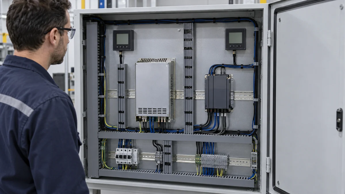
For a hypothetical 24 V branch carrying 20 A, suppose the combined outgoing and return conductors, connectors, and terminals drop 0.4 V. The branch dissipates 20 A × 0.4 V, or 8 W, along that path. The load receives about 23.6 V if the supply terminals remain at 24 V. This is an illustration, not a specification for a real cabinet. A high-resistance terminal can concentrate part of those eight watts in a small contact area, whereas long, correctly sized conductors spread their losses differently. Identical end-to-end voltage drops can therefore have different thermal consequences.
Before asking remote sense to compensate, determine where the drop occurs. A designed cable run and a loose connection are not equivalent engineering conditions. A branch that drops voltage only during actuator movement also calls for observations at that operating moment, not only a steady cabinet reading. Raising PSU output to hide a hot contact might restore the load-end reading while allowing local heating to continue. Source and load measurements should be interpreted together, and damaged connections require repair rather than voltage compensation.
What the feedback loop actually moves
Local regulation uses a voltage feedback point close to the PSU output. Remote sense moves the feedback observation to a documented point nearer the load. The supply sees that the load-end voltage is below its target and increases its own output, within the range allowed by its design. If the high-current path still drops 0.4 V, the source might have to sit approximately 0.4 V above the desired load voltage to deliver the target at that load. The energy loss in the distribution path remains; remote sense changes where regulation is held, not the resistance that caused the loss.
The sense pair is not a second high-current power feed. Its purpose is measurement. Its electrical reference, permitted routing, required local connections when the feature is unused, and failure behavior belong to the specific model’s manual. Treating sense terminals as generic positive and negative power terminals can damage equipment or defeat regulation. A blog illustration cannot establish safe pin assignments for an unknown supply.
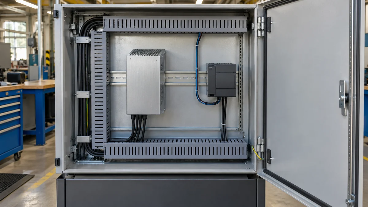
The location of the feedback point is a design choice with consequences. In a single dedicated load path, sensing at the equipment’s input may align with the actual voltage requirement. In a cabinet that branches to several loads, one chosen point can be held near target while other branches have different cable drops or operating currents. A remote-sense pair does not make all outlets regulated at their own terminals. The further the branches diverge electrically, the less useful one common feedback location is as a representation of every load.
Remote sense can also affect dynamic behavior. A long pair running through a noisy machine cabinet, a large downstream capacitance, or changing branch loads can interact with how a particular PSU’s feedback system responds. Good practice is model-specific, including routing and filtering instructions from the manufacturer. The general principle—measure at the point whose voltage matters—does not license arbitrary sense lead length or a home-built correction network.
Compensation is bounded, and cable heating is not compensated
Manufacturers specify how much distribution drop a remote-sense circuit can correct. That limit may be expressed as a voltage, as a percentage of nominal output, or with additional operating conditions. It is not an unlimited trim range. The official TDK-Lambda discussion of remote-sense limits and cable losses explicitly warns that exceeding a supply’s compensation range means the load-end voltage will no longer be regulated. It also points to reducing cable length or increasing conductor size when the distribution loss is excessive. The article’s numerical examples are teaching examples, not ratings to copy onto another supply.
There are at least three boundaries to check. First, the supply must have enough voltage headroom to raise its output while respecting its own specified output range. Second, the load and any other devices on the same bus must tolerate the source-end voltage, which can rise above the intended load-end value. Third, conductors, terminals, and protective devices still carry the same current and dissipate heat according to their resistance. Remote sense does not improve their current rating or eliminate a voltage drop across them.
The last boundary is often missed because the load begins working again. If the PSU moves its output upward, a meter at the intended sense point may report a good voltage. That does not show that every intermediate connection is cool, nor that the return path is healthy. An 8 W branch loss remains approximately 8 W at the illustrated 20 A and 0.4 V drop, even if the supply compensates the 0.4 V at the equipment. The precise distribution of heat still matters.
Sometimes lower-loss distribution is a better solution. A shorter route, larger appropriate conductor, fewer connection points, or moving conversion closer to the load can reduce drop without increasing source voltage. In other cases the layout cannot change and the remaining, documented drop is modest; remote sense can then be a useful way to maintain a sensitive load’s input voltage. The distinction is between correcting a known design loss and masking an abnormal or unsafe one.
The failure mode of the sense pair belongs in the design
A power path and a sense path can fail independently. A sense conductor may become open, intermittent, reversed, or connected to an unintended branch. The response is not universal. Some supplies provide local-sense fallback or protective behavior; others require defined local connections when remote sense is not used. The output may move or shut down differently depending on the product. No safe inference about an open sense lead can be made from the words “remote sense supported” alone.
A cabinet that is subject to vibration, service movement, or repeated terminal access deserves special attention at the low-current sense connections. A high-current output connector can remain intact while its nearby sense contact degrades, causing apparent regulation problems despite adequate source capacity. The converse is also possible: the sense pair remains connected and the PSU raises its output as resistance develops in the main conductor. This is why comparing source-end and load-end behavior can be more informative than watching one voltage indicator.
Incorrect feedback location can be just as misleading as an open wire. A sense pair attached before a long distribution branch reports the voltage before that branch, not at the distant device. It may be electrically functional but provide little benefit to the intended load. Cross-connection or an incorrect return reference can be more serious. Actual connections should follow the exact manufacturer drawing and be implemented by qualified personnel; this article does not specify a wiring procedure for an unidentified model.
On equipment with multiple supplies, the interaction can be more complicated. Two independently regulated units connected to a shared bus may not tolerate arbitrary sense points, trim settings, or current-sharing arrangements. A manufacturer-supported redundant system defines how the modules share current and where each senses the bus. Remote sense is not a method for improvising parallel operation. The relevant question is whether the complete approved assembly supports the intended regulation point under both normal and failed-module operation.
Decide whether the load needs this feature at all
Some industrial loads accept a relatively broad input range and do not benefit materially from a remote-sense loop. If the worst-case drop is small against that range, the extra sensing path can add integration complexity without improving useful performance. A load whose control electronics reset near the lower voltage limit may be different. The functional question is whether the load’s input must be held near a tighter value at its own terminals across the intended current, cable, temperature, and equipment operating states.
Temperature changes the distribution calculation because conductor resistance changes, and cabinet heat can alter both cable temperature and PSU operating conditions. Load current is also rarely fixed. A useful design comparison measures or estimates source-to-load drop at representative maximum demand rather than relying on a nominal idle state. Where a safety-critical machine function depends on the voltage, the applicable equipment and safety requirements take priority over a generic compensation rule.
Output accuracy in a datasheet must be read at its stated measurement boundary. A supply may promise a tight output tolerance at its terminals while making only a limited remote-sense claim, or it may specify load-end regulation under particular conditions. These are different statements. If the exact model has no remote-sense feature, one should not add external leads to an unrelated control input or assume a programmable output is equivalent. Conversely, an adjustable output can change the nominal source setting without continuously following a changing cable drop.
In a new cabinet, the best time to ask about remote sense is while the load locations and distribution branches are still being defined. The answer may lead to a shorter power route, a local DC–DC converter near a sensitive device, separate regulated branches, or a documented remote-sense arrangement. Once the system is built, a voltage problem first calls for evidence about where the drop occurs. The feature is valuable when it regulates a known, acceptable path loss at the load that matters. It is not a substitute for sound distribution hardware.