A “server power supply controller” is not necessarily one chip or one manager. The phrase can mean the control circuit inside an AC–DC PSU, a hot-swap or isolation controller in the power path, or the server’s BMC supervising power through a management interface. These functions have different authority. The PSU’s own control loops regulate its output and enforce its protection design. A host-side controller may manage connection to a shared bus. The BMC may observe status and request supported actions, but a software command is not a substitute for the converter’s local electrical protections. Identifying which controller owns the disputed behavior is the first step when integrating or diagnosing a managed server power system.
Conversion control remains inside the supply
The AC–DC module has to turn a varying input and load into a regulated output. Its internal control architecture may include analog circuitry, a digital controller, or both. In a representative design, separate stages shape input current, create isolation and a DC bus, and regulate the final output. Each stage responds to electrical feedback on a time scale appropriate to its task. That is why a BMC polling a management bus cannot close the main voltage-regulation loop simply by reading output-voltage telemetry.
When server processors change operating state, their point-of-load regulators and local capacitance respond first, while the PSU and distribution network replenish energy at their own rates. The PSU controller is responsible for maintaining its specified output behavior within its operating envelope. It may reduce output, shut down, or follow a defined restart policy when the module sees an internal overcurrent, overtemperature, or input condition. The exact threshold and recovery behavior depend on the actual PSU; a generic reference to “the controller” cannot supply those values.
The architecture can be easy to misread from a block diagram. A digital management interface on a PSU does not prove that its regulation loop is digitally controlled. Conversely, a digitally controlled converter may expose little host telemetry. Control implementation and management visibility are separate product attributes. The first belongs to the converter design; the second describes what an external system can learn or request. A replacement module should not be considered equivalent merely because both offer a PMBus connector.
The power-path controller protects the common bus
In a redundant server, each PSU must connect to the load without letting an unpowered or failed source pull down the shared output. That connection may be managed by circuitry within the module, on an intermediate PDB, or elsewhere in the host power assembly. A hot-swap controller, an ideal-diode or ORing circuit, current sensing, and switching devices may each be present in a particular design. Their exact placement is not universal. A buyer needs the approved platform power-path documentation, not a generic assumption that every redundant cage contains the same controller.
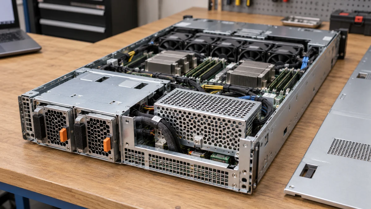
This domain deals with a different event from steady output regulation. During insertion, the power-path design has to control how a new source joins a live bus; when a source fails, it must prevent reverse energy flow and contain the fault according to the platform design. A controller that limits inrush or opens a switch under a fault does not make the AC–DC converter itself more efficient, and it does not decide the server’s workload policy. It is protecting a connection boundary.
The distinction becomes important in an apparent PSU failure. If one module reports a healthy internal output but the shared bus does not receive current from it, the problem could be downstream of the converter: a contact, isolation device, sensing path, or host enable condition. If the module never establishes its own regulated output, tracing only the PDB would start at the wrong boundary. BMC telemetry can narrow the area if the platform exposes separate source and bus measurements, but one summary “PSU fault” flag rarely identifies a failed component by itself.
Hot-swap controllers also have their own protection behavior. A controller intended to prevent excessive insertion current is not necessarily the same device that implements load sharing between two PSUs. Current sharing can be regulated inside modules, coordinated through a share bus, or handled according to another platform-specific method. A system may operate correctly with one module yet fail to preserve continuity when a second is inserted if the connection sequence and control boundaries are incompatible. This is a hardware behavior to qualify for a particular host, not a feature inferred from a familiar connector shape.
The BMC supervises rather than replacing local protection
The baseboard management controller observes and coordinates the server. Depending on the model, it may read PSU identity, input or output measurements, temperature, status bits, and fault history; it may also issue supported requests. Some host designs have additional firmware or management devices between the BMC and PSU. There is no universal list of commands that every server PSU accepts, and a displayed field may originate from a sensor elsewhere in the chassis.
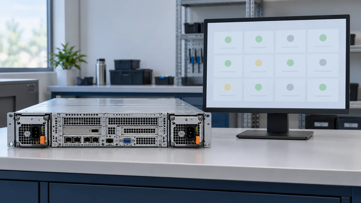
Management is slower and less direct than an electrical protection loop. The BMC can use information to warn an operator, change a platform power policy, or request an orderly response. A converter facing a severe local fault must act according to its hardware and firmware design even if the BMC is unavailable or the management bus is disconnected. Likewise, a host command to turn a rail on should not override the PSU’s input qualification or internal fault state. The difference is not merely organizational: it determines whether the server loses power abruptly, caps demand, or remains running after a module event.
The PMBus organization publishes separate application profiles for AC/DC server power supplies and hot-swap controllers. That separation is useful evidence that these managed devices have different jobs. It does not mean every product implements every profile command. A compatible integration needs the exact module command set, host behavior, electrical interface, and firmware support. “PMBus capable” is too broad to establish who may control an output, how faults are cleared, or whether a replacement will report status correctly.
For service teams, the most valuable distinction is between an observation and an instruction. Reading that a module is at a certain load is not the same as commanding its current share. Seeing a temperature alarm does not show that the host can set its fan below the module’s internal safe floor. A BMC may request reduced server load after a PSU is lost, but the surviving module still has to support the remaining electrical demand within its stated rating. Software policy can help prevent overload; it cannot create additional converter capacity.
One event can appear in three different control domains
Imagine a hypothetical server with two modules sharing a DC bus. One module develops an internal temperature fault. Its local controller may reduce or remove output according to its design. The power-path circuit then has to prevent that source from dragging down the common bus. The BMC might record a thermal or PSU event and, if supported, adjust workload policy or notify operations. These are sequentially related actions, but they are not performed by a single universal “PSU controller.” The server stays up only if the surviving source and distribution path can carry the load.
Now change the initiating event: the converter output is healthy, but a host-side connection device opens during an insertion transient. The BMC may again show a missing or failed module, while the source of the event is no longer the converter’s internal regulation. A third possibility is a management communication fault: power continues normally, but identity or telemetry disappears. Treating all three observations as a defective PSU can lead to unnecessary swaps and leave the actual bus or communications problem untouched.
The event order is often more informative than a single alarm. Did the module’s own output vanish before its current at the common bus fell? Did the host command a shutdown before the output changed? Did both the measured load and telemetry disappear, or only the telemetry? The available observations depend on the platform; not every server exposes independent measurements at each boundary. Where the data is limited, the correct conclusion may be “the failure domain is not yet resolved,” not a forced attribution to one controller.
That analysis does not require an operator to probe a live high-energy backplane. Use supported management records, documented platform diagnostics, and approved service procedures. Internal PSU and PDB testing belongs to qualified personnel with the appropriate equipment and manufacturer guidance. The purpose of distinguishing domains is to make the investigation safer and more precise, not to turn a blog article into a pinout or bypass procedure.
Authority limits become visible during replacement
Suppose a technician considers a new module with the same output voltage and sufficient faceplate wattage. It may still be incompatible with the host. The converter may have a different startup sequence or local protection response. The power-path interface may expect another insertion behavior, contact arrangement, or current-sharing method. The BMC may not recognize its identity or interpret status fields as intended. Any one of those differences can matter even if the new unit powers a bench load successfully.
That is why compatibility should be described by the exact supported PSU and host assembly, including firmware where relevant. Electrical output ratings tell only part of the story. The same chassis may allow different approved power options with different maximum configurations; it may also require matched modules. A host’s supported-parts list and technical product specification are better evidence than a generic category name. If those documents are unavailable, avoid claiming a substitute is hot-swappable or redundant merely from external dimensions.
Different controller domains also explain why a replacement can appear to work briefly. A module may establish regulated output, then be isolated because its connection behavior or host policy does not match the platform. Or it may carry load while the BMC labels it unknown, leaving the operator without reliable health data. The result should be assessed across electrical continuity and management visibility; neither alone proves full compatibility. Any decision to operate in a degraded or unsupported state belongs to the equipment owner under the OEM’s constraints.
Read a “controller” claim by its actual object
When a specification says a server PSU has a controller, ask what it controls. If the document discusses switching frequency, feedback, voltage regulation, and protection thresholds, it is describing converter control. If it discusses insertion current, an external switch, reverse-current blocking, or a common bus, it is describing a power-path controller. If it discusses addressable status, telemetry, alerts, and host requests, it is describing management. A product can include elements of more than one domain, and the boundaries may sit in different physical assemblies.
The wording matters because it constrains what the controller can solve. A BMC software update cannot repair a worn high-current contact. A hot-swap circuit cannot make a PSU’s internal thermal limit disappear. A sophisticated converter controller cannot guarantee that the host recognizes the module’s management interface. In an integrated server the control domains must cooperate, but each retains a different responsibility. Naming the controlled object and its physical boundary turns an ambiguous “server power supply controller” claim into a useful engineering statement.