A strong near-field probe peak beside a server power supply is evidence of local electromagnetic activity, not a radiated-emissions failure. The probe, its position and its orientation determine how much of that activity reaches the analyzer. Formal field-strength measurements ask a different question about the defined equipment configuration and receiving arrangement.
Radiated EMI emissions testing for server power supplies therefore needs a clear handoff between two observations: the frequency and operating condition that matter in an antenna measurement, and the local source that a probe helps investigate. A smaller probe peak can support a design hypothesis without proving a matching reduction in the server’s radiated field. Keeping those conclusions separate prevents a useful debugging tool from becoming an unsupported compliance verdict.
A local probe voltage is not the field-strength result
A spectrum analyzer displays the signal arriving at its input. With a near-field probe connected, that signal depends on the probe’s coupling to the nearby electric or magnetic field. Its frequency response, position, orientation, cable and any preamplifier influence the displayed amplitude. The number is not automatically the electric-field strength that a specified antenna arrangement would report.
A radiated measurement using a suitable antenna has its own measurement chain. Antenna response, cable loss, amplifier gain where used and receiver settings must be accounted for as required by the method. A field-strength result expressed in dBµV/m is not interchangeable with a receiver-port voltage expressed in dBµV. Sharing the same frequency axis does not make two traces equivalent measurements.
Nor can a generic correction factor turn every handheld probe reading into the server’s distant field. The spatial distribution close to a source differs from the radiation observed elsewhere, and the enclosure and attached conductors participate in that relationship. The probe identifies local activity through its own coupling; it does not automatically characterize the complete radiating structure.
Rohde & Schwarz’s Precompliance EMI Debug application note, version 1.00, separates antenna-based far-field testing from near-field probing used to locate hotspots. That distinction is the useful foundation here. This article supplies no regulatory limit, mandatory test distance or universal frequency range for a server.
Start with the emission that needs an explanation
If an antenna investigation identifies a suspect frequency, retain its equipment mode, receiving configuration and measurement settings before searching inside the design. A nearby probe peak at that frequency provides a candidate source. A large local peak at an unrelated frequency may be interesting, but it does not explain the original observation merely by being the largest signal on the screen.
Server assemblies contain several possible contributors: power conversion, board-level regulators, clocks and high-speed interfaces. A signal related to the PSU’s switching activity can appear at harmonics, while another circuit may produce a similar frequency. Frequency coincidence alone cannot identify which circuit drives the relevant radiated emission.
Operating-state correlation strengthens the investigation. Determine whether the antenna observation and local signal appear under the same stable equipment activity or transition. Use actual documented server modes rather than assuming two installed PSUs always share current equally. A supported reserve policy can place the two modules at different operating points.
A local signal that changes with a particular converter state becomes a better hypothesis, but still needs a connection to the observed emission. The emitting structure could involve a conductor or enclosure feature outside the probed area. A quiet-looking location is not necessarily irrelevant, and the strongest accessible hotspot is not automatically the dominant radiator.
The starting antenna result can itself require investigation. Ambient transmissions and instrument limitations may obscure the equipment contribution in an ordinary laboratory. A suitably documented background observation can help identify that ambiguity. It does not make an uncontrolled room equivalent to the prescribed test environment or justify treating every visible peak as server-generated.
Changing probes can change the ranking without changing the server
Near-field probes do not all sample the same area or field component. Electric-field probes respond to the electric field; magnetic-field probes commonly use loops. Probe selection changes what the instrument emphasizes. A comparison made with one probe type should not silently become a numerical comparison with a different type.
Rohde & Schwarz describes a practical sensitivity-versus-resolution tradeoff for magnetic loops: larger loops provide greater sensitivity, while smaller loops improve spatial resolution. A broad scan can locate an active region, followed by a smaller probe to distinguish nearby sources. The smaller probe’s lower reading does not establish that the design emitted less; the measurement tool changed.
Frequency response creates another ranking problem. The tallest peak in a probe spectrum need not identify the frequency with the largest radiated field or the smallest margin in an applicable antenna test. Probe response and local coupling can differ across frequencies. Use the antenna investigation to identify the frequencies that need explanation, then compare the local signals at those frequencies under recorded conditions. Reducing the largest local peak while ignoring the frequency of concern can consume development time without addressing the original problem.
Even a characterized probe does not eliminate this distinction. Knowing its response improves interpretation of its own measurement; it does not remove the spatial and structural differences between local coupling and the assembled server’s radiation.
Orientation matters too. Magnetic coupling is strongest when field lines pass through the loop and weakest when they lie parallel to its plane. Rotating the loop can therefore change a peak substantially with no change in the circuit. Preserve probe orientation and position when comparing a design modification rather than accepting the most convenient repeat placement.
Spacing and access are additional variables. Moving the probe away from a component changes coupling. Reaching a different spot after a cable or shield is moved can also change the observation. A reproducible fixture or carefully recorded probe relationship improves a relative comparison, but does not transform it into a standard field-strength test.
Keep the receiving chain unchanged as well. Added preamplification can reveal a weak signal, while changed attenuation, bandwidth or display settings can alter what is visible. Instrument overload and noise-floor limitations deserve attention before a small apparent improvement is interpreted. Retain the original settings with the trace so another engineer can understand the comparison.
Internal access must remain within the manufacturer’s permitted engineering arrangement. An energized server PSU can contain hazardous circuitry; a near-field probe is not permission to remove its enclosure or defeat required protective connections. Use approved accessible locations or a suitable controlled fixture operated by qualified personnel.
A smaller hotspot can coexist with an unchanged antenna result
Consider a hypothetical investigation in which a server has a suspect antenna peak and a local probe finds activity near its power assembly at the same frequency. Engineers make a supported design change and repeat the local measurement with the same probe arrangement. The peak falls. This observation supports a reduction in the signal coupled into that probe under those conditions.
It does not yet identify the change in the antenna measurement. The modification may have reduced a local field component that coupled weakly to the structure responsible for radiation. Another source may still dominate at the receiving antenna. The change may also alter coupling elsewhere in the assembly. These are possible explanations, not reported outcomes for any server or Powernexu product.
Return to the defined antenna arrangement and repeat the relevant equipment condition. If its peak also falls repeatably, the two observations support a relationship worth developing. They still do not establish that every change at the local probe transfers with the same amplitude ratio to the antenna. A single paired improvement is not a general conversion law.
If the antenna result remains unchanged, retain both findings. The local modification may be real and useful while failing to address the emission of concern. Searching for another source or coupling relationship is more informative than declaring the antenna test wrong because the hotspot became quieter.
| Observation | Supported conclusion | Unresolved question |
|---|---|---|
| Local peak decreases with unchanged probing | Less signal couples into that probe at the recorded location | Did the relevant radiated field decrease? |
| Antenna peak decreases in a repeatable comparison | The measured emission changed in that arrangement | Does the complete required assessment pass? |
| Local peak decreases but antenna peak does not | The observations describe different effects | Which source or coupling relationship still controls the antenna result? |
The server configuration belongs with the radiated observation
A standalone PSU feeding a simple load and the same PSU installed in a server are different electromagnetic arrangements. The host adds load activity, metalwork, interconnections and external cables. A component investigation can help identify a mechanism, but it cannot silently become a completed-server result.
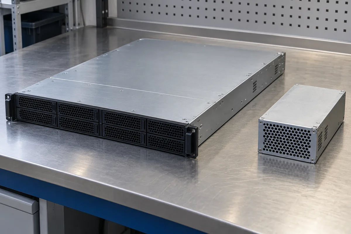
Texas Instruments’ June 2018 overview of radiated EMI specifications describes power-converter radiation as dependent on parasitic effects, layout and the surrounding system. Its published measurement examples also make receiving geometry and detector choice explicit. Those historical examples provide engineering context; their standard tables are not treated here as current requirements for an unspecified server.
During server diagnostics, record whether the enclosure is in its intended state and which cables and peripherals are connected. A lid removed for probing changes the configuration. It can be useful for locating a source, but a result collected that way should remain identified as diagnostic. Restore the required configuration for the corresponding antenna assessment.
Likewise, distinguish a steady operating mode from an intermittent event. A broad sweep may not capture a short-lived signal reliably. Time-correlated observation or suitable acquisition features can help identify when it occurs. The required detector, bandwidth, dwell and search procedure for a formal result come from the selected method, not from whichever instrument setting produces the cleanest trace.
The assembled system can also contain intentional transmitters or support equipment that need treatment under the applicable assessment plan. Do not identify an emission source merely from its proximity to the PSU or subtract an inconvenient signal without establishing what it represents. The measurement scope must remain visible.
Keep the debug finding narrower than the conformity claim
Precompliance work can reveal likely problems and guide design changes before formal assessment. Its evidential strength depends on the environment, equipment, method and configuration actually used. A receiver with a limit line displayed does not by itself establish that every required test condition was satisfied.
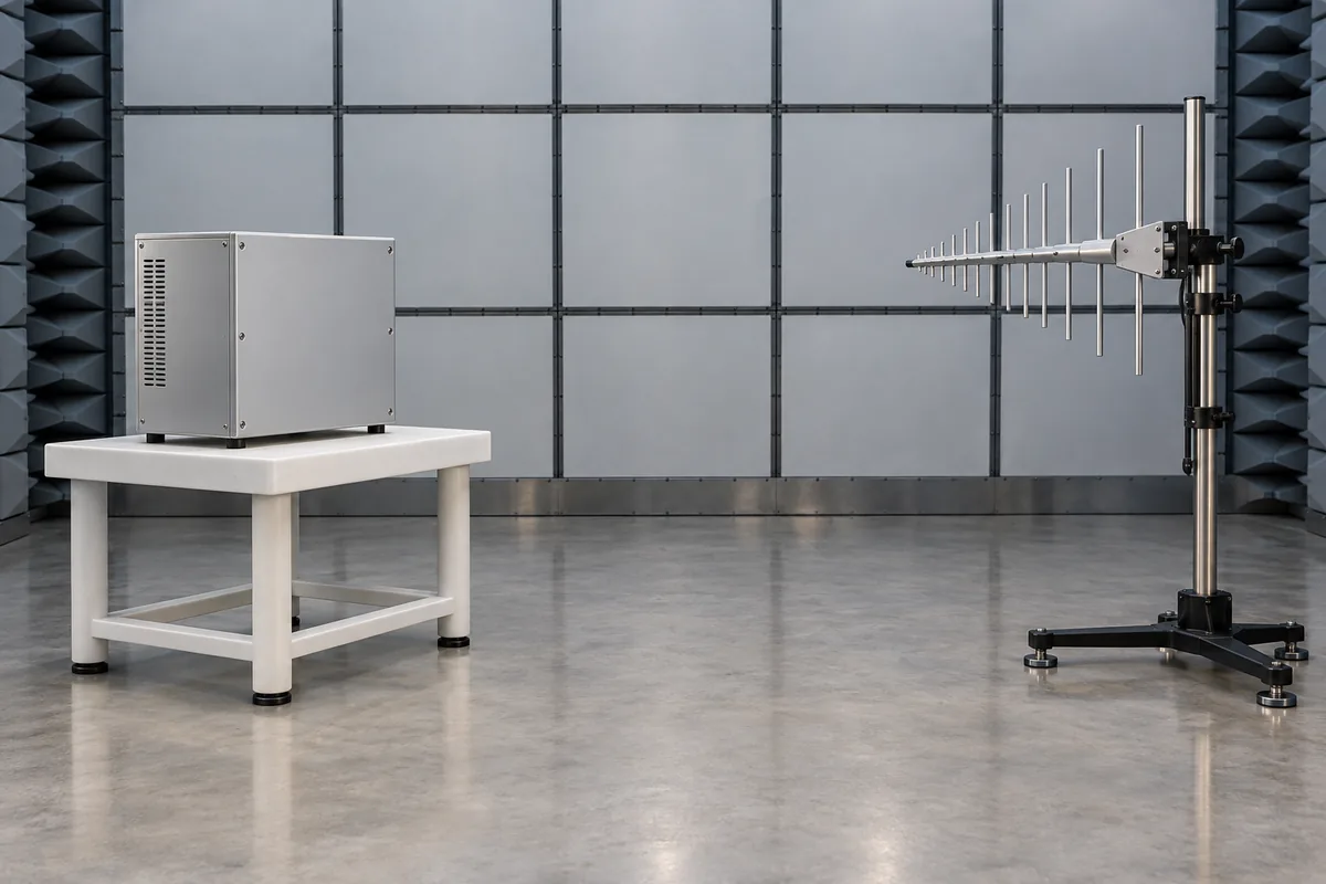
For formal work, the responsible EMC team or laboratory must establish the applicable equipment scope, standard edition, classification and measurement method. A component report, a near-field investigation and a completed-server radiated-emissions report answer different questions. This article assigns no certification status to a PSU or server.
The useful debug result is specific: which frequency and equipment state were investigated, where the probe coupled to the signal, what changed locally and whether the relevant antenna observation changed afterward. That relationship can direct the next engineering action without inventing a margin to an unverified limit.
A near-field probe earns its place by locating and comparing activity that a distant antenna cannot localize directly. Its strength is spatial diagnosis. Preserve that strength by reporting the actual local finding, then using the appropriate antenna measurement and formal assessment to answer the separate radiated-emissions question.