An industrial AC-DC power supply for analytical instruments must be sized for what the instrument’s converters draw, not merely for the power delivered to a detector or ion source. A high-voltage stage can supply a very small output current while placing a substantially larger input-current requirement on the low-voltage front end. Its voltage-programming signal is a third quantity, with a different electrical role.
XP Power’s MS Source datasheet provides a concrete mass-spectrometry example. The DC-to-high-voltage stage uses a nominal 24 V input, specifies a maximum input current of 2 A, and separately lists its high-voltage output and control characteristics. For the engineer selecting the upstream AC-DC supply, that input specification is the starting allocation. It is not a measured operating profile, an efficiency figure or a statement that the instrument becomes ready as soon as 24 V appears.
Put the converter input on the AC-DC load schedule
The relevant boundary runs from the AC-DC output to the high-voltage converter’s input terminals. In the MS Source example, the published input range is 22.8–25.2 VDC, with 24 V typical. The input-current entry is 2 A in the maximum column. These are requirements at the DC-to-high-voltage stage; they do not describe an AC mains input or a programming connector.
At nominal voltage, reserving 2 A corresponds to a 48 W input allocation. This is simply 24 V multiplied by 2 A. It is useful for organizing a front-end load schedule, provided the voltage and current constraints remain attached to the entry. Calling the stage a “48 W load” without those constraints would lose information: a supply offering enough total watts at the wrong voltage does not meet the stated input range.
The MS Source manufacturer datasheet, dated May 27, 2026, also lists output voltage, output current, turn-on time, polarity reversal and programming behavior. Those fields describe other boundaries and operating functions. None replaces the input-current entry when allocating the 24 V source. A purchasing description focused only on the high-voltage output can therefore understate the front-end requirement.
This matters in instruments containing several conversion stages. A detector supply, an ion-source supply, digital electronics and auxiliary equipment may all receive power from one low-voltage source. List each device at the point where it takes energy from that source. A downstream output rating cannot be inserted directly into the upstream schedule without the conversion information needed to translate between them.
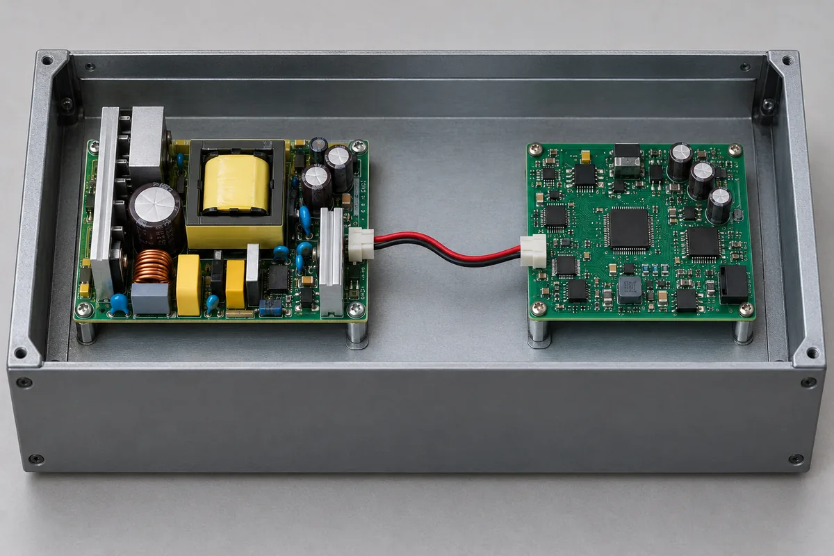
The example identifies a particular manufacturer’s downstream stage, not an approved pairing with a Powernexu supply. No interchangeability, instrument compatibility or installed performance follows from the arithmetic. The receiving converter’s exact documentation supplies the load-side requirement; an AC-DC candidate must independently meet that requirement under its own documented conditions.
The 48 W allocation does not explain where every watt goes
A maximum input-current entry can support a conservative purchasing allocation without supplying a complete energy model. The MS Source table does not provide an input-current waveform, a current-versus-output-setting curve or an efficiency map. The 48 W nominal allocation should therefore remain an allocation, rather than being reported as continuous measured consumption.
In particular, do not divide a chosen high-voltage output-power figure by that allocation and announce a conversion efficiency. The numerator and denominator would not be matched measurements at one operating point. A valid efficiency result needs simultaneous input and output energy or power under defined conditions, including the output setting, load and operating state.
There are several possible reasons why a precision converter’s input budget cannot be reconstructed from its useful output alone. Control electronics consume energy, conversion stages have losses, and changing an output voltage involves stored energy. Which effects dominate in this exact product is not established by its input-current limit. The safe inference is narrower: the manufacturer has supplied an input requirement that the upstream design must accommodate.
Nor does “maximum” reveal whether the greatest current occurs during initial startup, polarity reversal, a particular load or another condition. Without those conditions, assigning the entire 2 A to a supposed short pulse would be speculation. Assuming that it is drawn continuously would also overstate what has been documented. Retain the published limit and ask for the operating information needed if the design depends on a smaller allocation.
This distinction changes an engineering decision. A front end with sufficient documented capacity can be considered using the published input limit. A smaller front end justified by presumed low average consumption needs additional evidence. Its approval cannot rest on a small high-voltage output current, an unloaded bench observation or an assumed conversion efficiency.
Shared 24 V loads need a common operating state
Once the high-voltage converter has an input allocation, the remaining instrument loads must be added at the same boundary. Do not mix their DC input requirements with AC wall consumption or power delivered after another converter. That mistake can count losses twice in one branch and omit them entirely in another.
For a limited illustration, suppose a hypothetical instrument uses one MS Source stage and other electronics whose combined documented 24 V requirement is 1 A. Reserving the stage’s published 2 A and that hypothetical 1 A gives 3 A at the source boundary, or 72 W at nominal 24 V. The additional 1 A is an invented example assumption, not a measured instrument configuration or a specification for any product.
The calculation establishes only a simultaneous static allocation. It does not establish startup compatibility, transient response, allowable external capacitance or the current rating of a harness. Those are separate constraints, and their relevant values must come from the selected hardware. There is no universal percentage that converts this arithmetic into an approved analytical-instrument power design.
A smaller source might be possible if particular loads are demonstrably mutually exclusive. For example, a documented operating sequence could prevent two loads from reaching their largest demand together. That is a system property requiring evidence about the real states and control behavior. A software intention to avoid coincidence is insufficient if startup, recovery or a fault can energize both branches.
Conversely, adding individual maxima can be deliberately conservative when detailed operating profiles are unavailable. Keep that conservatism visible rather than presenting the result as expected consumption. It helps procurement distinguish a source sized against published limits from an energy estimate used to predict normal running cost or enclosure temperature.
Enclosure heat needs a different record again. The front-end allocation includes power passed to downstream loads, not just heat dissipated inside the AC-DC supply. Likewise, the high-voltage stage’s input allocation cannot all be assigned as local heat without knowing its actual operating point and energy delivered elsewhere. A thermal estimate based on maximum reserved input power may serve a deliberately conservative purpose, but it should be labeled accordingly. It must not masquerade as a measured heat load or be used to infer a cooling arrangement from the electrical schedule alone.
Power, programming and monitoring are separate interfaces
The MS Source datasheet specifies a 0–10 V analog voltage-programming input to control the high-voltage output from zero to full scale. Its nominal 24 V input supplies power. Equal use of the word “voltage” does not make those two connections alternatives. The controller sets the desired output through a signal path while the AC-DC front end provides the energy for conversion.
The same document identifies analog voltage and current monitor outputs, enable/inhibit control and polarity control. These functions let instrument electronics command and observe the high-voltage stage. They do not establish an AC-DC supply’s output-current capacity, and a valid command does not prove that the commanded high voltage has already settled.
There is also a relevant isolation statement: the datasheet says the input ground is internally connected to the output ground. The downstream converter therefore cannot be treated as adding an input-to-output galvanic-isolation barrier. Any required isolation arrangement must come from the actual instrument architecture and its applicable requirements, rather than from the large difference between its input and output voltages.
This is why a supply specification should identify the role of each connection instead of merely listing nominal voltages. A 24 V energy input, a 0–10 V command and a monitor scaled to full output each answer a different question. Connector details and grounding must follow the purchased configuration’s documentation; photographs of a closed enclosure cannot establish them.
Three time specifications answer three different readiness questions
The upstream AC-DC output becoming available begins a power sequence; it does not finish the instrument’s preparation for measurement. The MS Source table lists a maximum turn-on time of 2 seconds. It separately lists polarity reversal at 25 milliseconds, with a 5 millisecond option. These are different entries for different events.
Do not substitute the faster reversal figure for initial turn-on, or presume that an unspecified purchased unit includes the faster option. The table also does not give a complete instrument acquisition schedule. A voltage transition, an output reaching a required error band and an acquisition becoming analytically valid need not have the same endpoint.
XP Power’s mass-spectrometry discussion explains the application consequence: polarity switching and subsequent settling can force pauses between scans. That supports treating the high-voltage state as relevant to measurement timing. It does not establish an exact pause for a particular analyzer, nor authorize calculating throughput from one switching-time number alone.
The same datasheet gives a stability figure of 100 ppm per hour after a one-hour warm-up. That condition is distinct from both turn-on and polarity reversal. It is not a promise that the output is unusable for an hour, and it does not say that the complete instrument is calibrated after exactly one hour. It limits how the stated stability specification may be applied.
Temperature remains another condition. The table lists a typical temperature coefficient of 100 ppm per degree Celsius; it should not be rewritten as a guaranteed maximum. The specified operating-temperature range likewise does not establish constant analytical performance everywhere within it. The instrument’s thermal arrangement and its required measurement performance remain relevant after electrical startup.
The front-end specification should retain what remains unknown
For this example, the upstream requirement can state the MS Source input window and published maximum input current without pretending that its full load profile is known. Other loads then enter the schedule at their own input boundaries. If a candidate depends on reduced simultaneous demand or a benign startup pulse, those assumptions become requests for evidence rather than hidden reductions.
Keep the precision-conversion requirements alongside that schedule. The high-voltage stage owns its documented programming, reversal and stability behavior; the upstream source must provide its required input. This division prevents a low-ripple AC-DC catalog claim from being mistaken for an assurance of ion-source stability or a detector’s measurement performance.
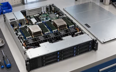
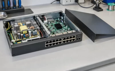
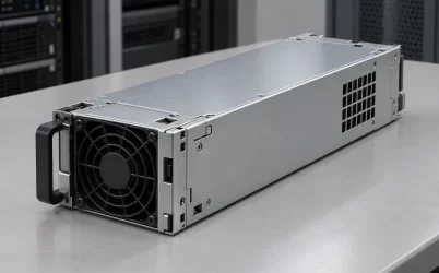
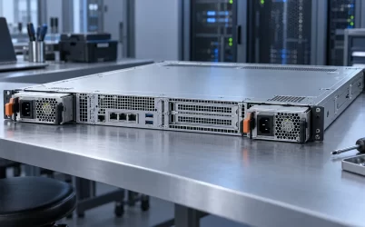
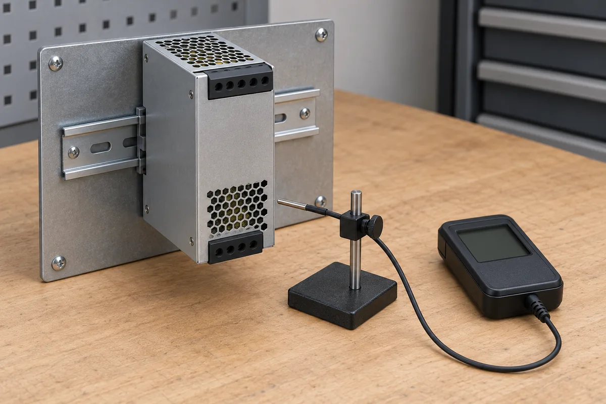
The illustrations here show generic power hardware and enclosure arrangements. They identify neither the MS Source product nor a particular analytical instrument, and they do not document an installed circuit or test result. The exact manufacturer datasheet remains the evidence for the stated electrical and timing entries.
A useful AC-DC choice therefore preserves two distinct conclusions: the front end has enough documented capability for the converters’ inputs, and the downstream stages satisfy their own precision functions under stated conditions. A small useful high-voltage output does not erase the first requirement. A healthy 24 V bus does not, by itself, establish the second.