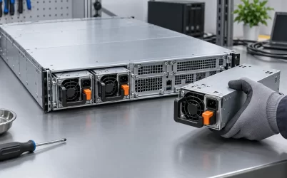
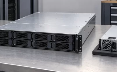
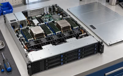
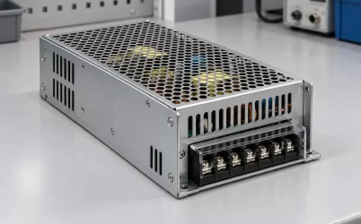
An open-frame power supply in a PoE switch is usually an upstream AC-to-DC converter, not the circuit that negotiates power with a camera, access point, or other Ethernet device. It feeds a DC bus inside the equipment; the power sourcing equipment (PSE) then detects and classifies connected devices, controls port power, and enforces its own budget. A board that provides a nominal 54V output cannot be called a complete PoE source merely because its voltage suits a PoE-oriented design. The useful question is how much of the board’s available power remains for the ports after the switch itself, conversion losses, limits and operating conditions are accounted for.
This distinction makes “PoE open-frame power supply” a different problem from selecting a generic exposed AC-DC board. The embedded switch has a defined Ethernet-port power promise and a protective enclosure. The board contributes one part of that promise. If the board output, PSE controller or thermal design is misunderstood, the switch may work with a few low-demand devices yet shed ports when several loads ask for power together. A bigger printed wattage number alone does not establish the behavior.
The 54V board is upstream of the Ethernet ports
Trace one device’s power path backward from the cable. The powered device receives energy over Ethernet pairs from a controlled PSE port. Inside the switch, port electronics decide whether that device is eligible and how much power can be allocated. Those electronics draw from one or more internal DC rails. An open-frame AC-DC board can create the main rail from the facility input, but it does not by itself perform detection, classification, per-port switching, cable-fault protection, or switch management. Those functions belong to the finished PoE equipment and its documented PSE design.
That is why the same board voltage can appear in two products with very different port capabilities. One switch may have a handful of low-power ports and ample controller headroom. Another may serve more demanding devices, reserve power conservatively, or share the DC bus with processors and cooling fans. The output voltage is a compatibility condition, not the available Ethernet power budget. Even two boards with the same voltage and nameplate watts may differ in thermal derating, transient behavior and mechanical integration.
Powernexu lists the GW-TO70WV54 open-frame supply with a 54V, 70W output and an input range stated on that product page. Its documented role is a compact AC-DC source for communication and PoE-related equipment. This is a relevant board example, not evidence that it independently implements an IEEE PoE PSE, fits a particular switch, or can deliver 70W at its Ethernet ports. Those system properties require the actual controller, port architecture, enclosure and operating conditions.
Where a port budget goes before a cable sees it
A switch must run its own electronics: processor, Ethernet PHYs, control circuitry, indicators and sometimes a fan. Power can also be lost in regulation stages, PSE switches, connectors and internal conductors before it leaves the ports. A nominal board rating therefore places an upper boundary on the system’s available input under the conditions in its datasheet. It does not equal the sum of advertised port outputs. The system budget must separately account for host consumption, conversion and distribution losses, any permitted peak behavior, and the maximum power that the PSE may allocate concurrently.
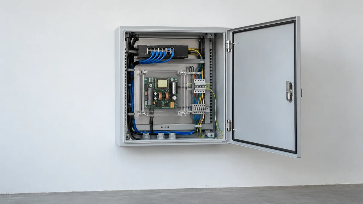
Consider a deliberately simplified example using a hypothetical 70W DC source. If the switch electronics consume 10W and internal power conversion and distribution consume another 5W at a particular operating point, at most 55W remains in that arithmetic for port allocation. If two ports are each reserved for 20W, only 15W remains under that example’s assumptions. This is not a specification for the Powernexu board, a real switch, or a standardized PoE class. It illustrates why a 70W source cannot be advertised as 70W of available port power without further evidence. Real losses and host demand vary with load and temperature.
Port policy adds another layer. Some PSEs allocate from the maximum class a powered device requests or from an administrator-set cap; others can use monitored consumption under a documented policy. The sum of current readings may be smaller than the reserved budget, because devices are not necessarily drawing their maximum at that instant. Conversely, apparent spare power today does not guarantee that every connected device can start together or survive a later demand increase. The exact PSE behavior is a feature of the switch and firmware, not the upstream board.
A Cisco industrial PoE design brief states the system-level point directly: power-supply selection determines the budget available for powered devices, and the switch’s own demand must be included. Cisco’s statement concerns the architecture it describes; it is not a rating method for a particular Powernexu module. Its practical implication is that a PoE-equipment specification should name both the accepted DC supply and the separately verified PSE port budget.
Cable-end power is another boundary
The power allocated at a switch port is not always the power delivered to the remote device. Current flowing through Ethernet cable conductors causes resistance loss; connectors and cable length contribute as well. A camera mounted far from the cabinet may therefore receive less power than the PSE releases at its output. The relevant limit for the device is what the applicable PoE standard, PSE and cable installation allow at its end, not simply the AC-DC board’s output wattage.
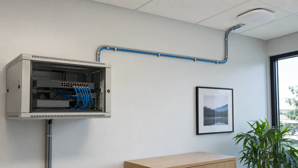
This matters when someone sizes the upstream board from endpoint labels. Adding the nameplate power of four remote devices is not necessarily a complete budget. The PSE may reserve a different amount for each port, cable losses must be allowed for under the intended arrangement, and the switch itself consumes power. A remote device may also draw more during initialization than in a quiet state. Each figure belongs at a distinct point in the chain: board DC output, PSE allocation, port output and powered-device input. Mixing the points leads to a calculation that may look conservative but is actually comparing unlike quantities.
Voltage drop inside the equipment can be important too. A board measured at its terminals may regulate correctly while a long, narrow internal conductor or overloaded connector leaves the PSE input below its permitted range during simultaneous port demand. Raising the source set point without checking the PSE’s allowed voltage and the board’s adjustment limit can create a new overvoltage problem at light load. The sounder response is a short, appropriately rated DC path and a verified voltage at the PSE under relevant load; the design still has to respect the actual product’s connection and safety rules.
The open board borrows its protection from the host
An open-frame converter is intended to live inside another enclosure. In a PoE switch or industrial network cabinet, that host must provide the needed barriers, mounting, grounding scheme, ingress protection and access control for the installation. The board’s own approval, if any, does not automatically approve the finished network equipment. Its live input area must not become accessible through a service opening or an exposed cable route. The exact protective construction follows the selected board’s documentation and the finished product’s applicable requirements.
The enclosure also changes cooling. A board tested with open air around it may run hotter behind a dense port panel, above another converter or next to a compact switch processor. Heat from the PoE power stages adds to the board’s own conversion loss. An internal fan may cool the processor while bypassing a capacitor or magnetic component on the PSU board. The rated output is usable only within the specified ambient, airflow and mounting conditions, including any derating. A board that supplies the required watts on an open workbench may not sustain them inside the finished sealed or wall-mounted case.
Startup is not the same as the steady PoE budget
When AC returns, the converter must establish its DC output while the switch’s input capacitors charge and its controller boots. The PSE may then energize ports in a defined sequence. A system whose steady demand is comfortably below the board rating can still encounter a startup event that exceeds its short-duration capability or makes the rail dip below what the controller needs. Whether that causes a retry, a delayed port enable, or a reset depends on the board and switch design. There is no generic inrush allowance that can be inferred from a 54V label.
Staggering port activation may help in a compatible switch, but it does not create additional continuous watts. If all remote devices eventually request their maximum permitted allocations, the established steady budget still has to hold. Likewise, adding a large capacitor to bridge a brief dip increases charging current when the supply starts. The board’s protection and the switch’s soft-start behavior must be considered together; an intuitive “more capacitance” fix can change the problem rather than remove it.
Different outage modes also matter. A local AC interruption can remove every port unless an upstream UPS or a supported DC backup path maintains the board input. A switch that has dual DC inputs may require source isolation and failover behavior that a single open-frame board does not provide. And a battery-backed controller rail does not necessarily keep high-power Ethernet ports online. Describe which functions are expected to continue through an outage—management, uplink and selected endpoints, or the full configured port load—before treating “backup power” as a single feature.
One board may serve a switch, not every PoE architecture
A low-port-count indoor switch and a high-density outdoor aggregation unit pose different source demands. In the first, a compact board may fit naturally within a protective host and leave enough room for separate PSE electronics. In the second, high simultaneous allocations, environmental sealing, surge exposure and thermal management may call for a different power architecture. Neither case can be resolved by asking for “a PoE board” without naming the board’s electrical role. The open-frame source is one component within the equipment.
It is tempting to translate 54V and 70W into a fixed count of cameras. That count cannot be stated honestly without the camera requests, PSE policy, switch overhead and loss allowance. Two modest endpoints may work comfortably while a single more demanding device plus host consumption approaches the limit. Alternatively, a board with a higher nameplate wattage may still be unusable because its mechanical format, insulation boundary, airflow direction or accepted AC input does not fit the switch. Electrical power and integration constraints are not interchangeable.
The most useful product comparison follows the actual architecture: the board’s documented continuous DC capacity in the intended enclosure, the PSE’s supported DC input and allocation behavior, and the permitted power at each Ethernet port. A verified Powernexu board page can identify the first component’s published facts; it cannot certify the other two. This division keeps product claims precise while still allowing a designer to reason about the completed system.
When the last port asks for power
Imagine a switch already serving several devices when one more remote radio starts and requests power. The upstream board sees increased total DC demand, but the PSE decides whether the new port may be allocated, and the cable determines what reaches the radio. If the requested allocation does not fit, the switch may decline or limit that port according to its documented policy. If it does fit on paper but the DC rail dips during simultaneous operation, the system has a source, distribution or transient problem that the allocation table alone cannot reveal.
This event is the clearest way to understand the phrase “PoE open-frame power supply.” The exposed AC-DC board should be specified as a regulated source inside a protected, cooled piece of equipment. The switch must independently define its port-power contract. Connecting the two through a realistic power budget—without treating board watts as cable-end watts—answers the question that a voltage label cannot: which devices can remain powered together, under the installation conditions that actually exist.