A power supply that trips a hipot tester has produced a failed test result, but the trip alone does not identify insulation breakdown. The instrument may have detected sustained conduction, capacitive charging during a DC ramp, an excessive AC capacitive load, or a problem in the test fixture. Conversely, a green indicator means little if the intended voltage never reached the intended insulation. Interpreting hipot dielectric withstand testing for server and industrial power supplies requires both the electrical result and the conditions that produced it.
The useful investigation starts with three questions: when did the trip occur, what voltage actually reached the test object, and which current criterion was active? Those questions connect the tester log to a controlled production or qualification method. They also prevent a costly mistake: changing a limit until a unit passes without establishing why the original test failed.
Read the event before diagnosing the insulation
A dielectric withstand test applies a prescribed electrical stress to a defined insulation path for a prescribed interval. The applicable product evaluation and approved manufacturing instructions establish the test conditions. A qualification test may investigate a design or assembly configuration, while a routine production test checks units against an established method. Their settings are not interchangeable merely because both are called hipot.
Separate the programmed sequence into voltage rise, hold, voltage reduction, and discharge where applicable. A trip during voltage rise presents a different diagnostic problem from a trip after the voltage has stabilized. Save the failure phase and elapsed time before resetting the instrument. A final current number without its time reference can hide the distinction between a brief transient and continuing conduction.
Also separate an instrument abort from the product failure mechanism. An overload, an interlock opening, or failure to establish the programmed output can terminate a sequence without demonstrating dielectric breakdown. The affected unit still lacks a valid completed test. It should remain under the site’s nonconformance controls while the laboratory identifies whether the cause lies in the product, fixture, instrument capability, or method.
This distinction is especially useful when a previously stable production process changes suddenly. A rise in failures after a fixture replacement suggests a different investigation from scattered failures following an assembly change. Neither pattern proves the cause. It identifies which records and controlled comparisons are most likely to explain it.
Why charging current can resemble a DC failure
A power supply’s insulation system includes capacitance. Some is inherent in transformers and construction; intentional EMI components may also connect the circuits involved in an approved test arrangement. During a changing DC voltage, capacitance draws charging current. For an ideal capacitor, current follows capacitance multiplied by the rate of voltage change. Faster voltage rise therefore creates more charging current for the same capacitance.
Once the applied DC voltage becomes steady, the ideal capacitive charging component falls away. Real insulation can additionally exhibit absorption and conductive current, so a practical trace need not settle instantaneously. A rising-voltage current peak and a later stabilized reading answer different questions. Treating the peak as though it were entirely steady insulation leakage can create a misleading diagnosis.
TDK-Lambda’s discussion of power supply dielectric strength testing identifies EMI Y capacitors as a reason current behavior matters and explains that gradual DC application allows charging without prematurely tripping the tester. That supports investigating ramp behavior; it does not authorize changing an approved ramp, current limit, or dwell on a production station.
A controlled engineering investigation can compare the recorded voltage and current histories with the approved settings and expected load. If the voltage rise is steeper than intended, investigate the program or instrument before blaming insulation. If capacitance changed because a filter option or assembly revision changed, the test method needs formal review against the applicable requirements. Quietly widening a limit would erase the evidence needed to understand the change.
A decay after the ramp is evidence consistent with charging behavior, not a certificate that the product is sound. An intermittent arc, contamination, or a fixture defect can create more complicated signatures. Preserve the original failed trace and the unit identity so an authorized investigation can distinguish these possibilities without replacing the first result with a favorable retest.
AC current and DC current are different observations
With AC excitation, capacitance continues to draw current as the waveform changes. A total-current measurement can therefore contain substantial capacitive current even when the conductive component is relatively small. Frequency and capacitance affect that current. Comparing two AC results requires the same relevant waveform and frequency, as well as the same product and fixture configuration.
DC testing can make the stabilized conductive component easier to examine after charging and absorption have diminished, but it introduces its own timing and discharge considerations. The two methods impose different voltage histories. They can also interact differently with components remaining in the test circuit. The fact that a DC result looks cleaner does not make DC an authorized substitute for an AC method.
Do not convert a published AC figure into a DC production setting using a generic multiplier. The approved test basis must explicitly support the selected waveform, voltage, polarity where applicable, duration, and arrangement. Similarly, a higher voltage for a shorter interval is not an automatic substitute for the documented test. A familiar rule from an application note can belong to conditions that differ from the selected product’s evaluation.
Tester capability matters here. A station can reach its output-current capability while driving a capacitive load and fail to maintain the requested voltage. The resulting event cannot be interpreted as successful exposure at that voltage. Review the instrument’s load limitations and measured output, rather than relying on a setpoint copied into a test record.
The timer and comparator belong in the evidence
Ramp time, hold time, and current comparison are separate controls. Whether the instrument evaluates current during voltage rise, applies a separate ramp criterion, or begins the hold timer after reaching the target must be established from the exact tester manual and program. Two stations with matching voltage and time fields can behave differently if these less visible settings differ.
For example, HIOKI identifies the 3153 as an AC/DC withstand and insulation-resistance tester with programmable steps and ramp timing. These are capabilities of that exact instrument, not evidence that any particular program is suitable for a server PSU. Its documentation also cautions that test times can differ from settings depending on the load. The practical lesson is to verify how a station implements the method rather than translating a procedure into superficially similar menu entries.
An upper current criterion normally addresses excessive measured current under specified conditions. A configured lower criterion may serve a different purpose, such as helping detect an unexpected absence of current in a validated fixture arrangement. A low reading is not automatically excellent insulation: an open connection can also remove the intended test object from the measurement. Connection verification needs its own documented basis.
Arc detection, if used, adds another observation whose meaning depends on the instrument and settings. An arc indication should not be silently relabeled as a steady leakage failure, nor dismissed because the average current was low. Record the actual failure code and preserve the associated settings. This lets the engineering review address the instrument’s decision instead of a technician’s shorthand description.
Trace the test object without turning the article into a hookup procedure
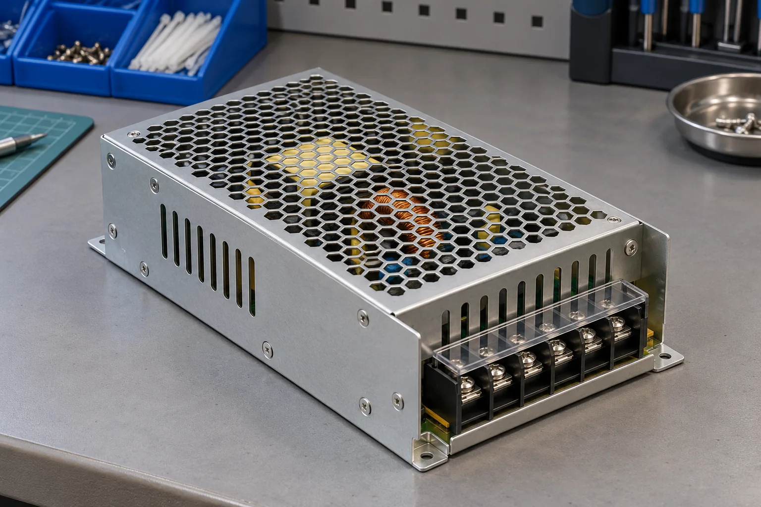
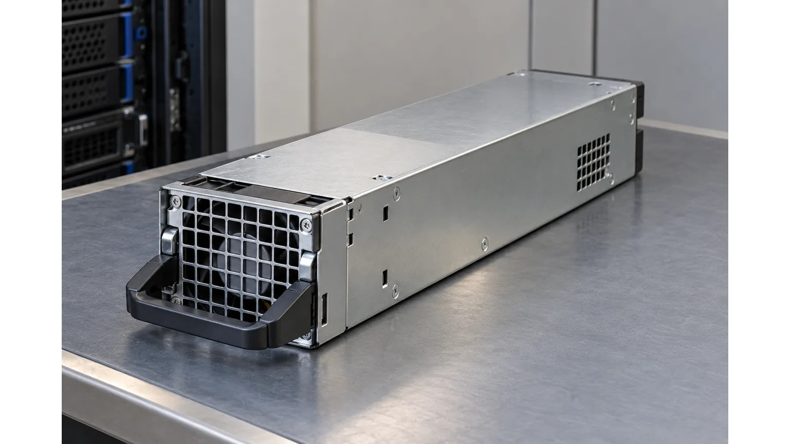
A standalone PSU, a redundant server power assembly, and an installed industrial supply are different test objects. Fixtures, distribution boards, EMI filters, chassis relationships, and attached electronics can alter the electrical network seen by the tester. A result from an assembled server cannot automatically be compared with a module-only factory record, even when the PSU part number is identical.
Use the approved test drawing to establish what remained connected and which manufacturer instructions applied. XP Power’s HPx installation manual illustrates the importance of this specificity: its customer dielectric-test sections distinguish different insulation paths and include restrictions for named HP-family variants. Those instructions belong to those products and configurations. They are not a general server or industrial power supply procedure.
High-voltage testing belongs in an appropriately controlled station operated by qualified personnel. Product configuration changes, any manufacturer-prescribed temporary test arrangement, and restoration checks must follow the authorized instructions. An apparent trip does not justify removing protective earth, defeating an interlock, or improvising connections. Residual stored charge must be addressed through the station’s documented discharge and safe-access process.
Fixture condition deserves the same attention as the product. Damaged insulation, contamination, worn contacts, or inconsistent positioning can introduce unintended paths or incomplete connections. Investigating these causes requires the laboratory’s safe inspection and verification methods. A useful comparison changes one controlled variable at a time and retains the original failure record; repeated high-voltage exposure without a diagnostic plan adds stress without reliably isolating the cause.
A test record that explains an unexpected trip
The record should let another qualified engineer reconstruct the electrical event without guessing. Include the exact PSU identity and revision, serial or traceability reference, assembly state, controlling procedure revision, fixture identity, instrument identity, and calibration status. Retain the actual program or its controlled identifier, not just a handwritten voltage copied from the display.
| Recorded observation | Question it helps resolve |
|---|---|
| Measured voltage, failure phase, and elapsed time | Did the intended exposure occur, and when did the event develop? |
| Current history and active comparator settings | Was the decision associated with ramp charging, the hold interval, or another criterion? |
| Waveform, AC frequency or DC polarity, and timing | Are results from two stations electrically comparable? |
| Fixture verification and connected assembly state | Was the intended product network actually tested? |
| Failure code, investigation, and authorized disposition | What evidence supports the treatment of the affected unit? |
Consider a hypothetical batch that begins failing during the DC rise immediately after a test-program transfer. The useful first comparison is the approved ramp and comparator behavior against the transferred program, supported by measured output and fixture verification. A later successful run after an undocumented adjustment would not explain the original event or establish which units received a valid exposure.
Keep environmental and handling observations when they are relevant to the investigation. A damp or contaminated fixture and a clean, conditioned fixture need not behave alike under high electrical stress. Record what was actually observed rather than assigning humidity or cleanliness as the cause from the trip alone. A causal claim requires supporting inspection or controlled comparison.
By contrast, a unit that exhibits sustained abnormal current during the authorized hold needs investigation of the product and test path, even if extending the ramp removes an earlier transient. The charging explanation cannot account for every failure. A credible disposition states what was found, which approved correction was made, and which controlled test established the resulting status.
For server and industrial power supply programs, that is the value of interpreting hipot results as recorded events. The laboratory can distinguish an incomplete test, a method or fixture problem, and evidence of a product defect while keeping the failed result traceable. The final record should explain the unit’s status through measured exposure and documented findings, rather than through the color of the tester’s last indicator.