In a hypothetical control cabinet, each of three industrial power supplies starts successfully on its own. When AC returns to the whole cabinet after a brief outage, the common breaker trips before the machine is ready. All three supplies can meet their assigned DC loads in normal operation. The selection question is whether their AC inputs can come back together on the installed branch, including after a short interruption.
Which startup event should you stagger?
Use staged AC startup when simultaneous inrush exceeds what the shared protection or source can tolerate, each stage can start with the existing current draw, and all required equipment can be ready by the deadline. Delaying DC enable shifts downstream startup. Credit it with reducing AC inrush only when evidence for the exact supply shows that effect. Assess first energization and reapplication after a brief outage separately.
Find where the cabinet loses power
One incoming protective device sits ahead of all three power supplies in this cabinet. Supply A powers the controller, B powers remote I/O, and C powers instrumentation. Each has its own DC load. At the incoming device, their AC input currents share the same path. That arrangement can produce a cabinet-wide interruption even though each DC circuit runs comfortably once its supply is up.
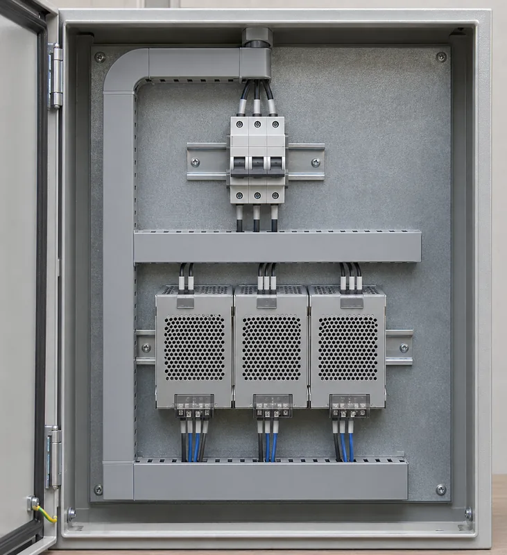
On the same event record, identify when AC reaches the PSU terminals, when the shared feed draws its startup current, and when the breaker indicates a trip. Add the DC enable command where one exists, the time each output becomes valid, and the point when the controller can see the I/O and instruments it needs. A controller event log can locate a missing device later in the sequence. A synchronized electrical record can show whether the feed had already opened by then.
The sequence determines which change is worth investigating. A high input-current pulse as AC reaches the terminals, followed by a confirmed breaker trip before DC comes up, points toward an AC energization problem. If AC remains within the candidates’ input limits and the DC rail drops when a load connects, investigate the output and its load. If the PSU terminals lose voltage while the breaker remains closed, check whether the upstream source entered current limit or disconnected.
MEAN WELL’s application FAQ describes the input pulse at AC power-on and warns that several units starting together can put the upstream source into protection. It separately describes output surges from loads such as motors and capacitive inputs. The two events can occur close together in a cabinet, and moving one can leave the other in place. See the MEAN WELL application FAQ, questions 9 and 14.
Compare three ways to restore the same cabinet
Each restart sequence has to restore the same three services by the same machine deadline. In this example, readiness means the controller has booted, the I/O is exchanging valid data, and the instrumentation is available to the controller. The timing figure compares the AC input-charging events. Determine separately when all required DC outputs are valid, and allow time after that milestone for whatever equipment startup remains.
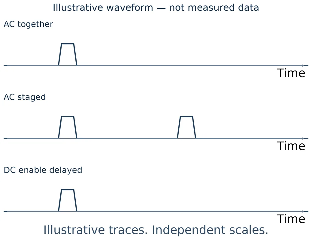
Apply AC to all three supplies together
When the common feed returns, AC reaches A, B, and C together. Their input charging intervals can overlap on the shared branch, even if the outputs rise at different times. Each supply starts its output automatically in this example. The arrangement adds no intentional waiting between AC applications, which leaves the most time available for downstream startup. It is a viable option when evidence covers the combined energization event and the branch, source, and supplies meet their respective limits.
The trip in the hypothetical cabinet puts that option in question with its present equipment. When comparing candidates, ask for input startup evidence before ranking them by DC wattage or by the size of a single published inrush number. A candidate with a lower listed peak may have a longer pulse or a different test condition. Its effect on the installed branch remains open until those differences are accounted for.
Apply AC to A first, then to B and C
A starts the controller while the AC feeds to B and C remain open. The controller can then permit AC to the second group once the specified staging conditions are met. This moves the second group’s input charging later and can remove its overlap with A’s initial pulse. B and C still energize together in the example. Their combined input event occurs on top of whatever current A and the other energized equipment are drawing at that point.
The later stage trades time for less overlap. The useful delay depends on A’s actual input-current history and on when the controller can make a valid switching decision. It also has to leave enough time for B and C to start and for their loads to become available. If the second group still exceeds what the shared branch can handle, splitting it into two stages changes both the electrical event and the time available for the last load.
Restore AC together and delay DC enable
In this version, AC reaches every input together, with the outputs held off until a later enable command. The comparison assumes an independently powered enable controller and supplies whose input charging proceeds while their outputs are disabled. Under those assumptions, the charging pulses can still overlap at AC return. The later command shifts when the converters serve their DC loads. An output startup surge can still occur at enable, especially if every output is released together.
For a real candidate, ask what its remote input actually controls, how the output defaults after loss and restoration of AC, and whether the manufacturer can provide AC-input current with the output disabled. If documentation shows that enable also governs an input-charging stage, use the documented sequence in the branch assessment. A signal name or a timing diagram that starts at DC output rise leaves that AC behavior unresolved.
A brief outage can leave the supplies in different states
A first energization after a long shutdown gives the manufacturer or test team one starting condition. A momentary drop after production can leave energy in the supply and leave components warm. The amount of charge remaining when AC comes back can alter the next charging pulse. If the design has an inrush limiter with a recovery or reset condition, that limiter’s state at reapplication can change the pulse as well. The combined result depends on the candidate design and the interruption.
Consider a brief outage in the example cabinet. A might keep the controller above its reset threshold under its actual load, while B’s I/O rail falls far enough to drop communications. Meanwhile, the AC switching device may have released. A controller that has stayed alive may still be able to command the stages, but its pre-outage state may describe a cabinet in which B and C were already on. The sequence needs a way to detect that the AC path or the equipment state changed.
Start with the interruptions the machine can plausibly see, such as a transfer between sources or a loss and rapid return of the cabinet feed. Record the observed or specified AC interruption at the PSU terminals. An upstream command to open and reclose and the terminal voltage history describe different parts of the event. In some cases the voltage dips without disappearing, which can lead to a different recovery sequence from a clean disconnect.
For each candidate supply, request data for the applicable input voltage and frequency, the previous operating state, the initial temperature or warm-up condition, and the off-time before reapplication. Ask how the manufacturer applied AC and whether closing phase and source impedance were controlled or varied. Check the DC load and enable state during the test as well. Mark which conditions are documented and which will need cabinet-level evidence.
For repeated interruptions, include the possible sequence of events. A second interruption can occur while only A is running or while the B and C group is starting. In the first case, the restart logic has to determine whether A is still valid and whether the next group is authorized. In the second, the state of B and C can differ from the state observed after a long shutdown. MEAN WELL cautions against rapid AC cycling. Ask the candidate manufacturer which repeated energization conditions it supports before treating an automatic retry as part of normal recovery.
Read the supply pulse against the installed AC equipment
A usable supplier submission identifies the candidate and gives either an input-current trace or enough information about magnitude, duration, and test conditions to interpret the event. Check whether a listed peak is typical or a documented limit for the stated setup. Some documentation may describe a single startup pulse while the installed sequence puts another pulse or rising load current nearby. Capture or request the portion of the event that the shared protection and source actually see.
On a shared single-phase feed, the current at the common point is the instantaneous sum of the currents on the downstream paths it supplies. A sum of individual peak values represents coincident peaks only under assumptions about their timing and the applicable conditions. Separate traces from a stiff laboratory source may also change when connected to the same installed source. A coincident pulse can pull down the shared voltage, which in turn can change the currents and the startup sequence.
For a breaker, obtain the applicable manufacturer’s response information for the exact installed device and setting, including its short-duration behavior and tolerances where provided. Check the time scale and the kind of current the manufacturer uses in that information. An oscilloscope’s instantaneous peak and a curve expressed on a different current basis require a supported way to compare them. Ask the protection manufacturer how to assess the waveform if the published data leave the brief event unresolved.
In a staged arrangement, check the switches that actually apply AC to each group. The contactor for B and C has to make their input charging current as well as carry their running current. Use the switching manufacturer’s applicable making and repetitive-duty information. Where an electronic source feeds the cabinet, obtain its transient current and voltage response and its recovery behavior. A sequence that avoids breaker operation can still leave the source sagging enough to delay a supply or restart the controller.
Supplier data can narrow the choice before a cabinet trial. For the remaining cabinet-level questions, arrange qualified acquisition of simultaneous branch current and PSU terminal voltage, with breaker or source status and DC readiness referenced to the same event. Include loads that actually share the upstream device during restoration. Preserve the supply population and source conditions with the result so that a capture from a partly populated panel is interpreted at its actual scope. Powernexu’s industrial power supply selection guide covers the baseline electrical, mechanical, and environmental requirements for the shortlist.
Make room for the last supply in the recovery budget
In the staged cabinet, A can receive AC directly when the feed returns. The controller it powers can command the switch for B and C if its program and switch-control path are already available at that point. If the switch coil instead depends on B, the proposed sequence has a circular dependency. Establish which source powers each part of the first switching action, including any interlock the controller has to read before it proceeds.
Trace the longest feasible path from the defined start of recovery to valid I/O and instrumentation. Include the time for the returning AC to meet the controller’s restore criteria, A to become usable, the controller to boot or recover, the later switch to operate, B and C to establish their outputs, and the downstream devices to initialize. Use actual dependencies to decide which intervals run in parallel. For delayed DC enable, include how the enable controller obtains power and establishes its initial command state.
There are two limits on when B and C can receive AC. The earliest permitted point comes from the shared branch’s response to their start while A is already drawing current. The latest point comes from the time B and C and their connected devices need to meet the machine deadline. A timer setting is feasible only if those limits leave room for variations in detection, switching, and equipment startup across the required conditions.
For example, the controller may be ready to issue a command before the source has settled after A starts. A readiness contact from A may confirm that A’s output is valid, while saying little about the shared source’s ability to accept the next pulse. Use that contact according to its documented meaning. If the sequence depends on source recovery too, establish a condition or interval that addresses it. After a second loss during staging, determine whether the logic restarts the sequence or can safely resume from the actual switch and load states.
In this cabinet, simultaneous return remains a candidate if the combined input event is supported for the required restoration states. Staging becomes an option when it reduces the input overlap and leaves enough time for B and C. If the allowable interval for staging disappears, the design has to change a physical constraint, such as the candidates’ documented input behavior or the arrangement of the shared AC feed. Adjusting only the DC enable delay can still help an output-side startup problem when the input event is already supported.
Frequently Asked Questions
Can I rank two supplies by their published inrush peaks?
Use the peaks for an initial screen when their definitions and test conditions are comparable. If the device decision is sensitive to pulse width, phase at application, or warm reapplication, get the corresponding data for both candidates. Keep a typical reading identified as typical when a supplier gives no bound.
Does a one-supply bench test support any part of the choice?
Yes. It can establish how that unit started under the recorded source, off-time, load, and enable conditions. A test with AC applied while the output is disabled can also show whether an input pulse occurred in that state. The shared-branch decision requires evidence for the installed supplies and their combined sequence.
Can I use the programmed transfer delay as the PSU off-time?
Use it to identify a case to investigate. To match the case to manufacturer data, determine when each PSU actually loses usable AC and when its input sees power return. Switching delays, contact behavior, and a residual or sagging source voltage can make the terminal event differ from the programmed interval.
Does a replacement with the same DC ratings inherit the restart approval?
Carry forward the cabinet requirement and assess the replacement’s input startup conditions, reapplication behavior, and time to valid output. The replacement may draw a different pulse or become ready later. Even when only C changes, its new startup behavior affects the B and C group and can change the margin at the common upstream device.