A data center can have separate A and B power paths while a critical appliance still depends on one outlet. To implement redundant power for that single-corded load, bring both suitable sources to a transfer arrangement that supplies its one input. Then identify what remains shared after the sources converge. The transfer equipment, output distribution, cord, and appliance power supply form a different resilience boundary from the two incoming paths.
This distinction matters when adding a management switch, security appliance, monitoring gateway, or legacy storage device to an otherwise redundant rack. Buying another upstream power source does not give that appliance another inlet. The practical question is where to join the paths, how much equipment should share that junction, and which interruptions the service must tolerate. Those choices determine whether the implementation supports the intended maintenance and failure scenarios.
Start with the service that would disappear
Inventory the single-corded equipment by operational role, rather than treating every inlet as equally critical. Record the equipment identity, installed power arrangement, normal source, outlet assignment, and dependent services. Include small devices that enable recovery: an out-of-band gateway may draw little power yet provide the access needed when the main network is unavailable. Its importance comes from that dependency, not its electrical size.
Ask what happens if each device stops. A redundant pair of application servers may remain powered but become unreachable through a single shared network appliance. Conversely, a nonessential console display may be allowed to restart without affecting production. This service map prevents spending transfer capacity on convenient loads while leaving a less visible dependency on one source.
Separate three objectives in the project brief: survival of an upstream source loss, continuity during planned source maintenance, and survival of a failure in the equipment itself. A transfer device can address the first two under its supported conditions. It does not give the connected appliance a second internal power supply. If appliance failure also has to be tolerated, consider a supported redundant appliance arrangement or replacement equipment with an appropriate power architecture.
Write a specific boundary statement, such as: “These management appliances must remain operational when either approved incoming supply is unavailable.” Add any permitted restart or service recovery interval. This is more useful than labeling the rack redundant, because it gives designers and operators an observable objective without implying protection against unrelated failures.
Choose where the two sources converge
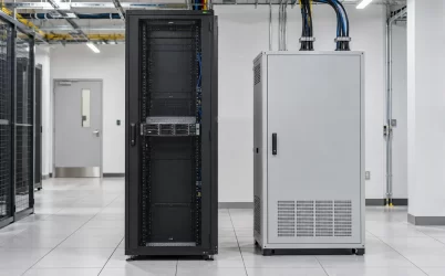
A local transfer arrangement serves an individual device or a limited rack group. A centralized arrangement supplies a larger downstream distribution area. Both can present one output supply to single-corded equipment; they place the shared equipment in different locations and expose different groups to its loss. Compare the actual output grouping before comparing product features.
Schneider Electric’s White Paper 62, Revision 1 discusses powering single-corded equipment from dual paths, including rack transfer equipment and larger static transfer switches. It identifies the larger load impact associated with failure of a larger shared switch. That architectural observation is useful here; the paper’s historical product examples and numerical characteristics should not substitute for current equipment documentation.
Consider a hypothetical deployment with several racks of management appliances. One centralized output can simplify the physical location of transfer equipment, but it also gathers those appliances behind a common element. Separate local devices can divide that exposure into smaller groups. The latter arrangement adds more equipment identities, alarms, settings, and maintenance tasks. Neither layout deserves a universal preference: the service grouping and the team’s ability to operate it matter.
Location also changes expansion. Adding another local group may allow a staged deployment, while a centralized installation may require reserved downstream capacity and distribution space. Draw the expected next expansion on the same diagram as the initial installation. Otherwise, an initially separate group may later be plugged into the nearest available output and quietly enlarge the common failure boundary.
Compare the recovery scope as well as the outage scope. If one local transfer device needs replacement, the affected appliances and available service alternatives should be identifiable without investigating every rack. A centralized unit may require a broader maintenance window or a different recovery arrangement. Translate each proposed grouping into a concrete operational sentence: which service owner receives the outage notice, which devices require intervention, and which unaffected services remain available. This exercise can reveal that a physically convenient group crosses several service responsibilities. It also gives procurement a useful requirement for maintenance access and replacement planning, rather than an unsupported demand for a particular transfer technology.
Keep related service dependencies visible when assigning groups. Dividing appliances evenly by wattage can still place both members of a service pair behind one shared output. Where the service architecture supports independent appliances, preserving that independence in their power assignments may be more valuable than achieving a visually balanced outlet schedule.
Follow the common output all the way to the appliance
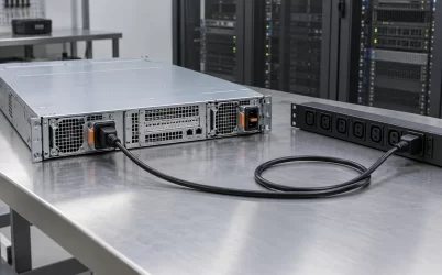
Mark the convergence point on a one-line drawing, then trace every component from that point to the load. Include output protection, any distribution strip, connectors, extension arrangements permitted by the installation design, the final cord, and the appliance inlet. A diagram ending at the transfer switch misses the portion of the path that both incoming sources now share.
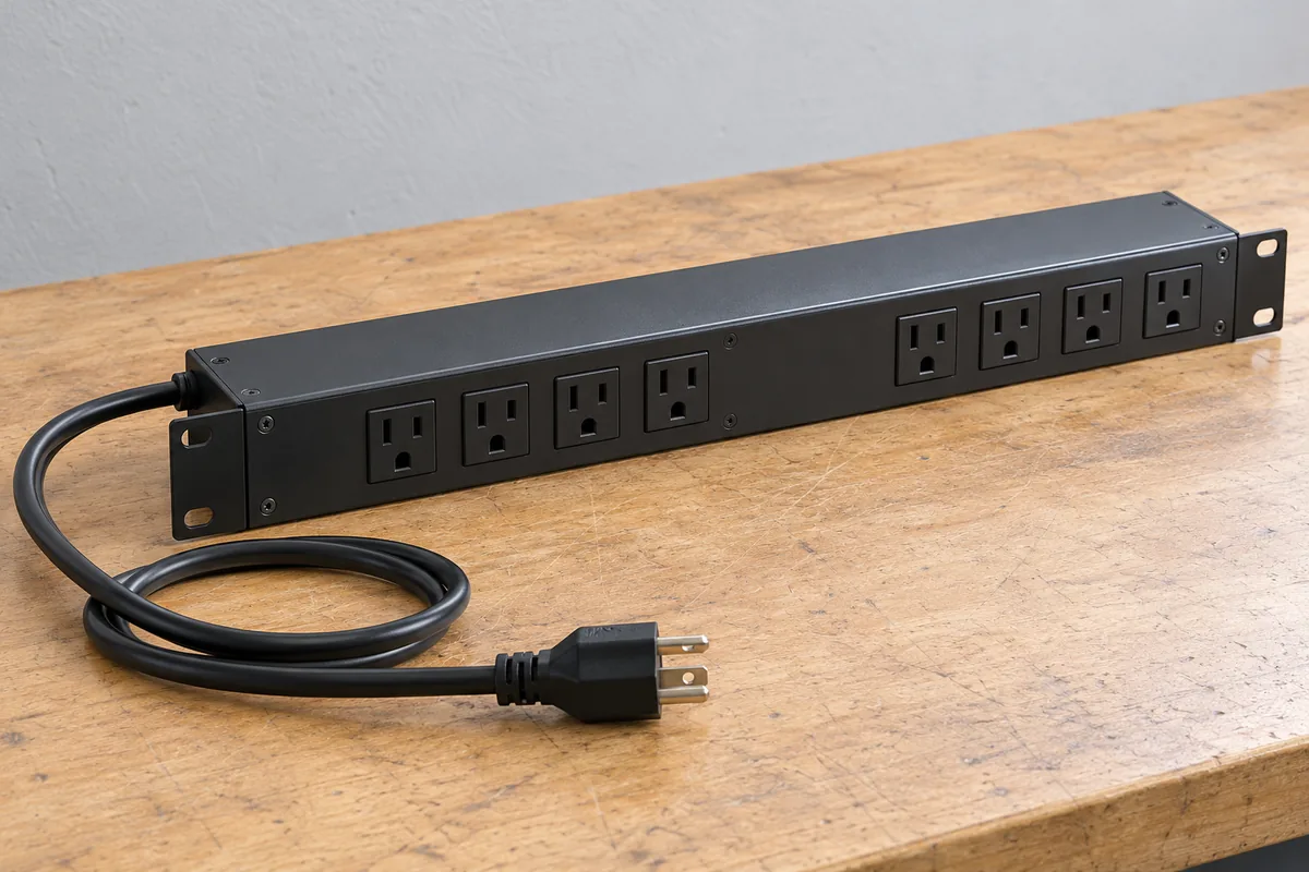
For each common component, ask which loads lose power if it is unavailable and how it can be serviced. An output strip shared by several appliances creates a grouping even when the transfer device itself has multiple outlets. Physical outlet count is not evidence that the internal distribution paths are independent. Obtain the manufacturer’s distribution information when that distinction affects the design.
Protection needs a separate review. An upstream alternate source does not automatically make a downstream fault harmless, and a transfer function should not be assumed to clear that fault. The responsible electrical designer must evaluate the installed protective arrangement and equipment behavior. The detailed branch coordination question belongs in the discussion of server branch circuits and PDU trip selectivity; here, the implementation task is to identify which downstream loads share that exposure.
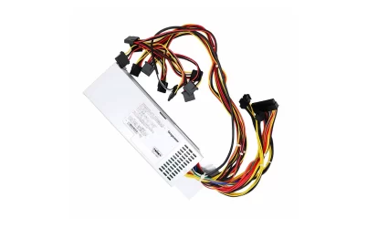
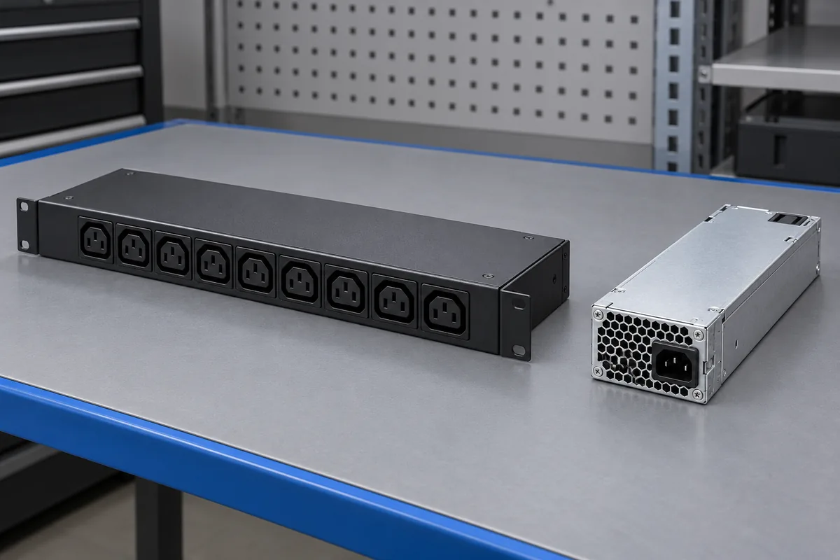
Also distinguish an appliance’s cord from its internal conversion stage. If the single internal PSU fails, changing the source supplying its cord may not restore operation. A spare appliance, documented configuration backup, or supported service pair addresses a different recovery need. Record that remaining dependency explicitly rather than allowing the presence of two incoming cords at the transfer equipment to conceal it.
Match transfer behavior to the installed load
Do not specify uninterrupted operation from the word “automatic” or from the transfer technology name. Obtain the exact transfer device’s documentation and the appliance’s input requirements. Review source acceptance, transfer and retransfer behavior, permitted source relationships, output configuration, load suitability, and behavior when neither source is acceptable. Features from a different model or firmware version do not establish those properties for the proposed unit.
A transfer event can include an interruption that the connected equipment must tolerate. Avoid assigning a universal ride-through allowance to servers, switches, or other electronic loads. The installed appliance, its PSU, operating load, input conditions, and transfer event all affect the question. Where manufacturer evidence does not establish continuity, the unresolved issue is load compatibility under the proposed conditions, not a missing marketing claim.
Define what “remained operational” means before observing a transfer. A front-panel power light is weak evidence for a network appliance whose interfaces restart or whose management session disappears. Useful observations may include service reachability, interface state, application behavior, reboot records, and power-event logs. Select observations that reveal the service interruption the project is meant to prevent.
Review the alternate source as an operating supply, not merely a cable connected to an input. Its available capacity must support the assigned transferred load under the facility’s design conditions. Account for other loads that move or remain on that source during the same event. Keep the electrical capacity study distinct from the service continuity observation: successful switching at one light load does not establish the installation’s full operating envelope.
Source restoration deserves attention as well. Determine whether the device returns automatically to a preferred input, waits, or requires an operator action in its configured mode. A device that survives the initial source loss may later transfer again. Include that second event in the operating description so the maintenance team understands the complete sequence.
Plan how the transfer equipment itself will be serviced
Two inputs can support maintenance of an upstream path while leaving maintenance of the shared transfer equipment unresolved. Ask how that equipment is isolated, removed, repaired, and returned to service. Review any bypass arrangement against the exact manufacturer documentation and installed design. A bypass is not automatically a redundant operating state, and its existence does not establish continuity throughout every service operation.
Document the supply condition during each maintenance state. Which source carries the appliance? Which protective devices remain in the path? What happens if that source becomes unavailable while the other path or the transfer equipment is being serviced? These questions expose degraded operation without relying on an ambiguous “maintenance supported” label.
For an existing rack, migration may be the first unavoidable interruption. A single-corded appliance cannot be presumed to keep running while its only cord is moved from an existing outlet to new transfer equipment. Plan a suitable service window or use a supported application-level alternative. Installing redundant upstream equipment does not retroactively make the physical reconnection interruption-free.
Assign a named owner to source preference, alarm routing, and configuration records. Facilities personnel may own the incoming supplies while an IT team owns the rack device. Without a clear handoff, each team can reasonably believe the other is monitoring the alternate input. Give both teams a shared record of the normal configuration and the conditions requiring action.
Keep the dependency map accurate after installation
Use the finished installation record to connect equipment identity, incoming sources, shared output group, appliance outlet, and service owner. Labels should let an operator follow the same relationship physically. Record configuration and firmware identity where they affect behavior, together with the evidence supporting the intended source-loss and maintenance scenarios. Preserve unresolved limitations as operating constraints.
Monitor loss of the alternate input even when the appliance remains healthy on its preferred supply. Normal service can conceal a degraded power arrangement. Route the alarm to someone able to investigate the source and restore the intended configuration; an unowned dashboard warning provides little operational benefit. Where supported, separate source condition alarms from equipment fault alarms so the response reaches the right team.
Make moves and additions trigger a small review of the dependency map. A replacement appliance may have a different input arrangement or restart behavior. An added distribution strip may combine previously separate service groups. A temporary outlet move during maintenance can become permanent unless the restoration record identifies it. These changes can alter the intended boundary without changing the transfer equipment.
The useful result is a precise implementation: identified single-corded services receive approved A and B sources through a documented transfer arrangement, and operators know the remaining common path. If a shared output, cord, or appliance PSU still threatens an unacceptable service outage, address that dependency through equipment or service architecture. Adding another source upstream of the same junction does not remove the junction.