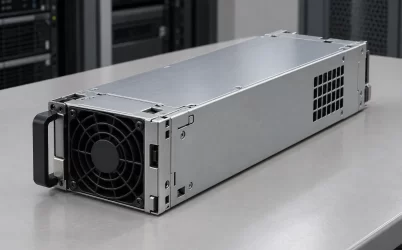
A usable G1231-0800WNA PDB load budget cannot be established from the available public evidence. Powernexu’s 800 W figure and rail-current entries are unverified seller claims, not confirmed output ceilings or branch limits. Gospower confirms a G1231 1U 1+1 PDB family, but its official page does not identify the -0800WNA suffix or establish that candidate’s electrical ratings, dimensions, or approved PSU pairing. Qualification therefore starts with the host’s load requirements and ends with controlled documentation for the exact board-and-module assembly.
Separate family evidence from seller claims
Gospower’s official G1231 page describes a 1U 1+1 power distribution backplane family that can be combined with 185 mm CRPS power supplies and can provide standard ATX or customized outputs. This supports a family-level description, not compatibility with every 185 mm CRPS module. The page does not publish exact-model power, rail currents, combined-load limits, dimensions, or PSU pairing for G1231-0800WNA. Other highlights on that page cannot be assigned to the suffix without an explicit manufacturer connection.
The Powernexu G1231-0800WNA seller listing is a sourcing lead, not manufacturer confirmation. Its claims of 800 W, +12 V at 65 A, +5 V at 25 A, +3.3 V at 25 A, -12 V at 0.5 A, and +5 V standby at 3 A are all unverified seller data. None is established as an available output ceiling, a connector or branch maximum, or a simultaneous-load allowance. Its AC-input field likewise does not establish the input interface of the bare PDB.
The available manufacturer material does not verify the full suffix. G1231-0800WNA should therefore be treated as a candidate identifier requiring verification, not described as an official Gospower model. Exact-model manufacturer documentation must take precedence over seller fields when determining what can be ordered and safely used.
A PDB is not the power supply module
A power supply unit converts its approved input into regulated DC. A PDB receives power through the module interface and distributes it to host connectors or harnesses. Depending on the design, it may also contain auxiliary conversion, protection, power-combining circuitry, or control functions. The available evidence does not establish which functions are implemented in the -0800WNA candidate.
This distinction matters when a listing loosely calls a product a “power supply.” An offer could contain a bare board, a board with harnesses, a complete redundant assembly, or an individual PSU cartridge. Neither an AC-input field nor a seller power claim identifies the contents of the shipment or proves that mains power connects directly to the PDB.
Before assessing capacity, identify the exact board revision, all installed PSU modules, the harness set, and the approved assembly configuration. The electrical ratings must describe that configuration rather than an unspecified combination of related parts.
Build the load table from the host
Record what the host requires at the PDB output interfaces before comparing it with any supplier specification. Use host documentation, component input specifications, and measurements at defined electrical boundaries. Processor or memory power estimates may exclude motherboard regulator losses; an AC wall measurement includes PSU conversion losses and cannot be entered directly as a DC rail load.
A practical load table should contain the following fields:
| Field | What to record |
|---|---|
| Load and operating state | The motherboard, drives, fans, adapters, management functions, and other loads in standby, startup, sustained operation, recovery, and required fault states. |
| Actual input rail | The rail used at the host interface, established from its pinout and input specification rather than inferred from the component name. |
| Connector and harness branch | The physical route supplying the load, including shared connectors or branches. |
| Demand and evidence | Continuous current or power, peak demand, transient duration, and the specification or measurement supporting each entry. |
| Conditions and concurrency | Input conditions, temperature, permitted configurations, and which loads can occur together. |
Group the entries by actual rail and physical branch, then define credible simultaneous operating cases. Startup and recovery can differ from sustained workload because drives, fans, or other devices may demand power together. Account for distribution losses consistently with the chosen measurement boundary, and document any design margin separately from verified hardware capacity.
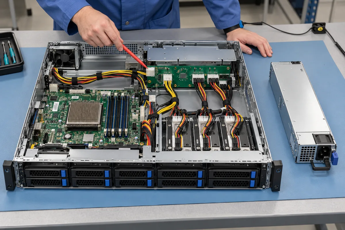
This illustration shows a load-mapping method: trace host demand through its connectors and branches, then compare it with the approved assembly’s limits. It does not establish a G1231-0800WNA pinout or routing arrangement.
Rail entries and 1+1 do not establish available capacity
A rail-current list does not show which currents are permitted simultaneously. Auxiliary rails may share conversion capacity, multiple outputs may share a total limit, and operating conditions may impose further restrictions. Even a verified rail rating would not automatically be the rating of each connector carrying that rail. Unused capacity on one branch cannot compensate for an overloaded connector elsewhere.
Qualification requires an exact-assembly rating table that states total output, rail limits, combined-load conditions, connector or branch limits, and relevant derating. The host’s simultaneous load cases must satisfy all of those constraints. Adding seller-listed rail entries or comparing the host total with the seller’s unverified 800 W claim cannot establish compliance.
The official family’s 1+1 description also does not establish surviving capacity. In a conventional redundant arrangement, the intended protected load must remain supported after either source becomes unavailable. Module count alone does not reveal that load, the installed module ratings, current-sharing behavior, or the limits of the remaining distribution path.
Obtain the approved single-module operating envelope at the intended input and thermal conditions, together with failure and hot-swap behavior. Review the load-transfer transient as well as sustained demand. A shared backplane, output connector, or harness can remain a common failure point; two modules do not by themselves prove fault isolation for every host rail.
Verify standby origin and control behavior
The seller’s standby entry does not identify where standby power is generated. It might originate in a PSU module, local conversion, or another assembly element; the available evidence does not resolve this. Nor does it establish standby availability with only one module installed or during module removal.
If the host needs management access while its main outputs are off, verify standby loading, regulation, and continuity in that state. Confirm the connector pinout and any required enable, power-good, presence, fault, or management signals, including their electrical levels, timing, and sequencing. A similar main-output rating cannot compensate for incompatible standby or control behavior.
Request controlled interface specifications and timing or state documentation for the exact assembly. Do not infer those requirements from rail names or from family-level hot-swap language.
Review connectors, harnesses, fit, and cooling
Electrical qualification must follow the complete power path. Check approved connector types and pin assignments, contact ratings, populated contact count, cable gauge, harness length, terminations, and branch protection. Similar-looking connectors can have different pinouts or current capability, so visual resemblance is not a compatibility test.
Local heating depends on current, contact resistance, and cooling, not just aggregate output. Review voltage drop and temperature rise under the host’s worst credible loads, including the required one-module condition. Validate the intended airflow, inlet temperature, enclosure arrangement, and any manufacturer derating. An infrared inspection can help locate heating during testing, but it does not replace controlled ratings or electrical validation.
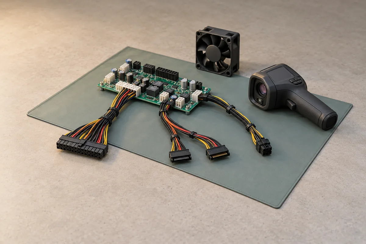
This is a harness and connector inspection illustration, not a state diagram or evidence of the candidate board’s actual layout. It highlights branch routing, connector differences, airflow, and thermal inspection.
Mechanical fit also requires an exact-revision drawing: board outline, mounting points, connector locations, mating geometry, clearances, and service access. The official family’s 1U description does not supply the -0800WNA candidate’s dimensions.
Require an approved pairing and document package before ordering
For a replacement, begin with the installed board label, host service documentation, and the system integrator’s approved spare number. Ask the supplier to connect the offered identifier and revision to manufacturer-controlled records. The G1231 family’s possible use with 185 mm CRPS supplies is not an approved-module list and does not establish electrical or control compatibility.
Before ordering, obtain:
- Identity and scope: manufacturer confirmation of the full identifier and revision, assembly part number, and bill of materials specifying the board, harnesses, and included PSU modules.
- Electrical ratings: total output, rail and branch limits, simultaneous-load rules, regulation requirements, and input- and temperature-dependent derating for the exact assembly.
- Approved PSU pairing: permitted module models and revisions, interface requirements, and any restrictions on mixed modules or firmware.
- Redundancy and control records: supported load after either module is unavailable, current-sharing and isolation behavior, hot-swap requirements, standby operation, and signal timing.
- Mechanical and thermal records: controlled drawings, connector and harness specifications, installation requirements, and applicable qualification results.
Compare that package with every defined host load state before approving the purchase. If the supplier cannot verify the full suffix or provide the required operating limits, the candidate remains unqualified for the host. The public evidence currently supports the G1231 family architecture and identifies seller claims to investigate; it does not provide a usable G1231-0800WNA load envelope.