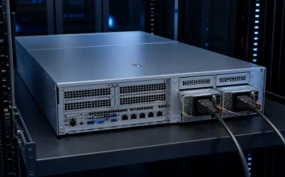
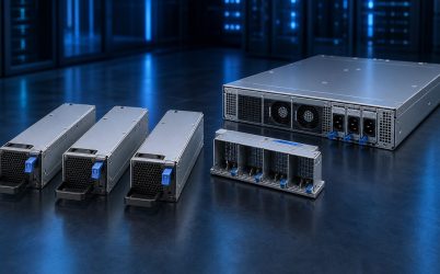
A 750W dual hot-plug redundant server power supply is most useful in a compact server whose maximum sustained DC demand can remain inside one module’s usable output envelope. With both modules online, the pair normally shares the load; after either module, AC feed, or input cord is lost, the remaining module must carry the server without exceeding its supported limit under the actual input and thermal conditions. The phrase therefore describes a 1+1 availability arrangement, not a 1,500W source for normal operation. It is a natural fit for balanced CPU, memory, storage, and modest accelerator configurations, but the chassis, PDB, firmware, and exact module family determine compatibility.
Why 750W occupies a distinct server design zone
The 750W class sits between low-power appliance supplies and the much higher ratings used for dense accelerator platforms. That middle position is important. It can support substantial enterprise compute or storage without automatically imposing the input-current, cooling, and rear-panel demands associated with kilowatt-class modules. At the same time, 750W is high enough that power allocation needs to be explicit rather than inferred from CPU thermal design power alone.
Typical candidates include compact dual-socket servers with restrained CPU power limits, single-socket systems with many memory channels, storage servers with a significant drive population, network appliances, and edge servers carrying one moderate accelerator. These are application patterns, not guarantees. A configured server may fall above or below the class depending on processor settings, DIMM count, fans, drive spin-up behavior, PCIe cards, and workload transients.
The attraction is balance. Two modules can share a moderate normal load at an efficient operating point while preserving one-module continuity. A higher-rated pair may offer more expansion room, but it can also change module length, platform support, airflow, input requirements, and light-load behavior. The useful question is not whether 750W sounds ample. It is whether the server’s degraded-state load remains a comfortable resident of the 750W operating envelope.
The surviving module owns the capacity calculation
In a 1+1 arrangement, the design limit is set by one module, because redundancy is meaningful only while the system continues operating after one power path disappears. If a server draws 520W at the DC bus in its heaviest credible sustained state, two healthy modules might each provide roughly half under balanced sharing. When one module is removed, the other must accept essentially the whole 520W plus any short-term transition demand that reaches it. The pair has two 750W nameplates, but its protected capacity remains one module’s supported output.
This distinction prevents a common sizing error. Adding two module ratings produces an installed nameplate total, not necessarily usable redundant capacity. The surviving envelope may also be lower than the front label under a particular low-line input, elevated inlet temperature, altitude, airflow condition, or vendor-defined derating rule. Those boundaries are model-specific and belong in the chosen module’s documentation.
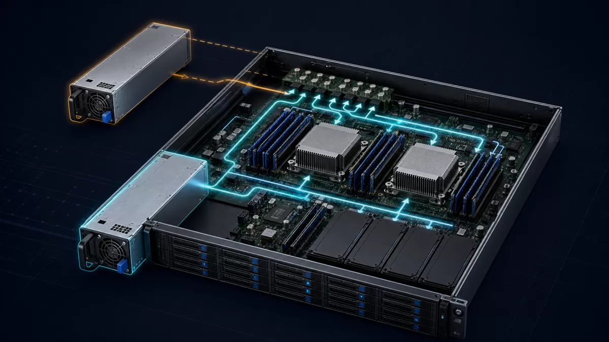
A useful load model separates sustained demand from short-duration events. Sustained demand includes the configured processors, memory, storage, cards, fans, motherboard conversion losses, and auxiliary rails at the intended workload. Event demand includes simultaneous drive spin-up, fan acceleration, processor boost, accelerator transitions, and the instant current transfer following a module loss. The platform may manage some of these events through firmware or power capping, but that behavior must be supported rather than assumed.
| Operating condition | What the 750W pair is doing | Capacity implication |
|---|---|---|
| Both modules healthy | Modules commonly share the server load | Normal per-module loading can be well below 750W |
| One module or feed lost | The surviving path carries the server | Protected load must fit one module’s usable envelope |
| Replacement inserted | Inrush and control sequencing occur before stable sharing | PDB and module family must support live insertion |
| Workload expands later | Normal and degraded loading both rise | Memory, drives, cards, and power limits can consume reserve |
Balanced loads suit 750W better than concentrated peaks
Two servers with the same average consumption can behave very differently on a 750W redundant pair. A storage or general-purpose compute server may distribute demand across CPUs, memory, drives, and fans, producing a comparatively steady bus load. An accelerator-heavy machine can present abrupt steps concentrated on a few high-current connectors and downstream voltage regulators. The second case may stress transient response and connector paths even when a management dashboard reports a reasonable average.
This is why 750W is often a better architectural match for compact, balanced configurations than for a build selected around maximum accelerator count. A moderate GPU or other PCIe device may fit if the platform officially supports it and the combined envelope remains controlled. Multiple high-power accelerators, aggressive CPU boost settings, or substantial future expansion can quickly move the design into another PSU class.
Power capping can make a configuration more predictable, particularly in edge or enterprise fleets where peak performance is less valuable than continuity. Yet a cap is part of the operating policy, not free capacity. The BMC and system firmware must apply it consistently during boot, failure, and recovery states. A maintenance event that transfers the load to one module should not depend on an informal software setting that disappears after a firmware reset.
Low-line input can redraw the 750W boundary
The wattage printed on a module does not by itself prove that the full rating is available at every supported input. Some designs provide the same output across their input range; others have a lower output limit in part of that range. Input current also increases as input voltage falls for the same delivered power. The consequence reaches beyond the module into cords, receptacles, rack PDUs, breakers, and facility planning.
For genuine feed redundancy, the two modules should not merely occupy separate bays. Their cords need to reach the intended A and B sources, and each remaining source must support the server after the opposite path is lost. If both cords terminate on the same rack PDU or upstream circuit, the server may tolerate a module failure but not that shared electrical failure.
The exact 750W module documentation should state supported input type and range, any input-dependent rating, connector type, and applicable efficiency data. An AC module is not interchangeable with a nominally similar DC-input module. Likewise, a replacement listing that mentions “750W” and “hot swap” can still be wrong for the platform because the electrical and management interfaces differ.
The PDB decides whether the nameplate reaches the server
Hot-plug modules normally mate with a power distribution board or related backplane rather than with standard desktop motherboard leads. That board combines or isolates module outputs, routes high current to the system, carries standby and control signals, and may connect management communication to the BMC. Its copper paths, connectors, protection devices, and cable assemblies form part of the current limit.
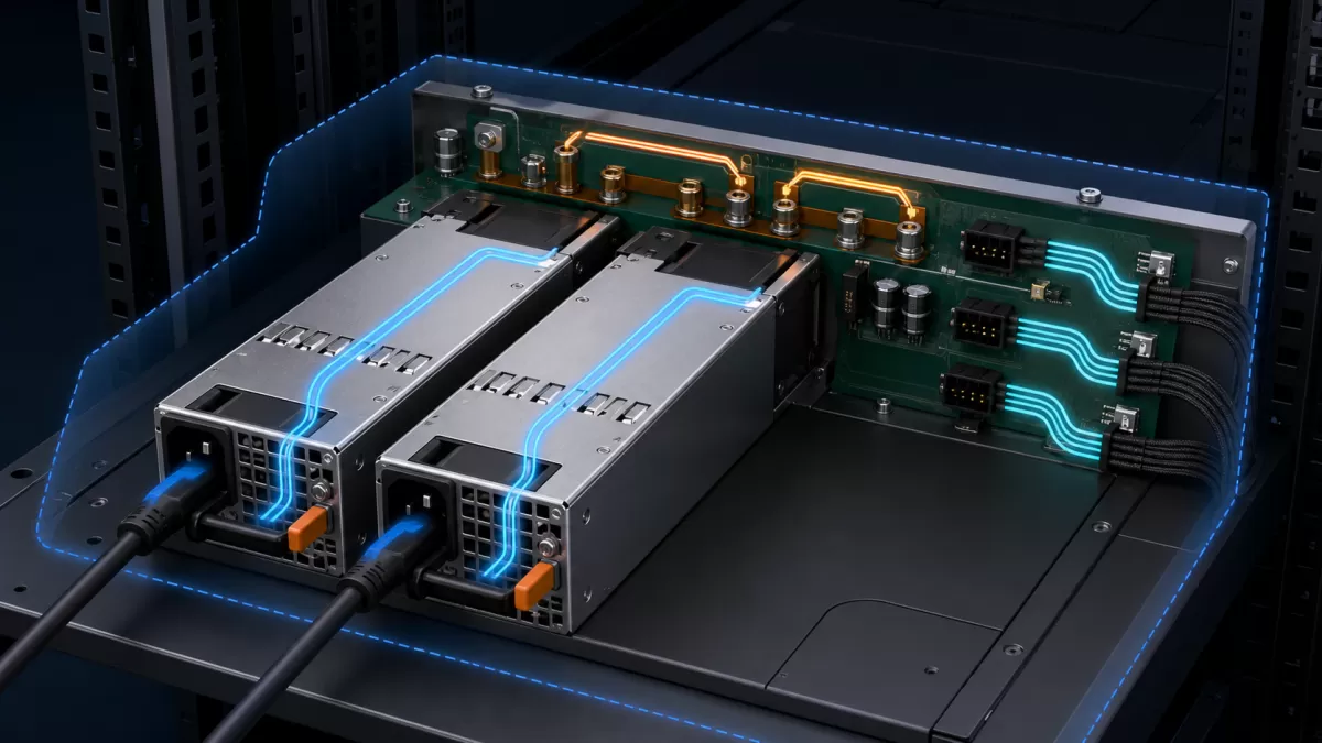
At a nominal 12V bus, 750W corresponds mathematically to 62.5A before considering any separate standby allocation or model-specific definition of rated output. That arithmetic is useful for appreciating the current scale, but it is not permission to assign 62.5A to an unknown connector. The module may use another output architecture, and the approved interface may divide current across multiple contacts and downstream branches. Only the platform documentation and exact component data can establish those limits.
Connector loading can therefore exclude an otherwise plausible configuration. A PDB output allocated to a PCIe card, CPU regulator, or drive harness has its own boundary. Adapters that rearrange contacts do not increase that boundary and can introduce resistance, heating, or incorrect sense behavior. The correct integration follows the supported PDB and harness topology from the module bay to every load branch.
Management compatibility matters as well. Presence, fault status, fan commands, telemetry, and inventory data may travel through platform-specific implementations even when PMBus is involved. A mechanically fitting module that powers the bus but generates persistent faults, runs its fan incorrectly, or fails platform authentication is not a sound spare.
Hot-plug is an event, not a removable handle
A handle and blind-mate connector make service possible, but safe live replacement depends on coordinated electrical behavior. During removal, the departing module must stop contributing without dragging down the shared bus. The remaining module and PDB must contain the transition. During insertion, connector sequencing, inrush control, standby power, control logic, and output enable behavior must prevent the new module from disturbing the running server.
Current sharing also changes state. Before removal, two modules may be balanced. Immediately afterward, one carries the full load. After a matching replacement becomes ready, the pair must return to stable sharing without oscillation or an excessive bus disturbance. These functions are properties of an approved module-and-platform combination; “hot-plug” on a marketplace title cannot establish them.
Operationally, replacement should preserve airflow. An empty PSU bay can become a bypass path that reduces cooling through the active module or server components. The failed unit or the platform’s specified blanking solution should be handled according to the server service procedure, and the replacement should match the supported family and firmware policy.
Mechanical fit and airflow are part of usable output
Compact redundant modules use small, high-speed fans and narrow airflow passages. The server chassis supplies a defined pressure environment and inlet-air path; a module qualified in one chassis cannot be assumed to deliver the same thermal performance in another enclosure. Rear cable congestion, blocked exhaust, recirculation, dust loading, and high rack inlet temperature can all reduce thermal headroom.
Physical compatibility includes more than height. Module width, depth, latch location, keying, extraction clearance, connector position, insertion force, and airflow direction must align with the bay. Even supplies described with the same general form factor may belong to different generations or interface families. For a spare purchase, the server’s official option or supported replacement identifier is stronger evidence than a matching wattage and similar photograph.
For custom server development, the module drawing, mating connector specification, PDB implementation, airflow curve, and derating information need to be treated as one interface package. For an existing branded server, follow its supported configuration matrix rather than reconstructing compatibility from generic CRPS terminology. Powernexu’s overview of CRPS architecture explains why common form factors improve integration without making every module interchangeable.
Where this power class makes architectural sense
A 750W redundant pair is compelling when a server’s worst credible degraded-state demand sits below the documented single-module envelope with enough room for the platform’s dynamics and environment. In that territory, the design offers live service and feed separation without moving automatically to a larger power class. It is especially coherent for controlled enterprise compute, storage, network, and edge configurations where expansion is bounded.
It becomes less attractive when the bill of materials is still growing, accelerator demand dominates the load, low-line operation reduces available output, or the intended PDB and connectors cannot carry the needed branches. In those cases, a higher supported module class or a different server power architecture may create a cleaner system than trying to recover capacity through adapters or optimistic power caps.
The neighboring server PSU wattage methodology can help build a configuration-level load model, while the CRPS PDB interface guide covers the assembly boundary in greater depth. For the 750W dual hot-plug case, the decisive picture remains simple: both modules share a compact server in normal operation, one module can support it after a failure, and every interface between the wall and the load preserves that promise.